[wpfilebase tag=file id=122 tpl=supplement /]
When transmitting audio signals between digital audio hardware devices, you need to decide whether to transmit in digital or analog format. Transmitting in analog involves performing analog-to-digital conversions coming into the devices and digital-to-analog conversions coming out of the devices. As described in Section 5.2.1, you pay for this strategy with increased latency in your audio system. You may also pay for this in a loss of quality in your audio signal as a result of multiple quantization errors and a loss of frequency range if each digital device is using a different sampling rate. If you practice good gain structure (essentially, controlling amplitude changes from one device to the next) and keep all your sampling rates consistent, the loss of quality is minimal, but it is still something to consider when using analog interconnects. (See Chapter 8 for more on setting gain structure.)
Interconnecting these devices digitally can remove the latency and potential signal loss of analog interconnects, but digital transmission introduces a new set of problems, such as timing. There are several different digital audio transmission protocols, but all involve essentially the same basic process in handling data streams. The signal is transmitted as a stream of small blocks or frames of data containing the audio sample along with timing, channel information, and error correction bits. These data blocks are a constant stream of bits moving down a cable. The stream of bits is only meaningful when it gets split back up into the blocks containing the sample data in the same way it was sent out. If the stream is split up in the wrong place, the data block is invalid. To solve this problem, each digital device has a clock that runs at the speed of the sampling rate defined for the audio stream. This clock is called a word clock. Every time the clock ticks, the digital device grabs a new block of data – sometimes called an audio word – from the audio stream. If the device receiving the digital audio stream has a word clock that is running in sync with the word clock of the device sending the digital audio stream, each block that is transmitted is received and interpreted correctly. If the word clock of the receiving devices falls out of sync, it starts chopping up the blocks in the wrong place and the audio data will be invalid.
Even the most expensive word clock circuit is imperfect. This imperfection is measured in parts per million (ppm), and can be up to 50 ppm even in good quality equipment. At a sampling rate of 44.1 kHz, this equates to a potential drift of $$44100\ast \frac{50}{1000000}\approx 2.2$$ samples per second. Even if two word clocks start at precisely the same time, they are likely to drift at different rates and thus will eventually be out of sync. To avoid the errors that result from word clock drift, you need to synchronize the word clocks of all your digital devices. There are three basic strategies for word clock synchronization. The strategy you choose depends on the capability of the equipment you are using.
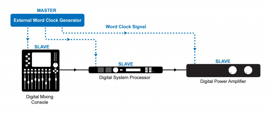
The first word clock synchronization strategy is to slave all your digital devices to a dedicated word clock generator. Any time you can go with a dedicated hardware solution, chances are good that the hardware is going to be pretty reliable. If the box only has to do one thing, it will probably be able to do it well. A dedicated word clock generator has a very stable word clock signal and several output connectors to send that word clock signal to all the devices in your system. It may also have the ability to generate and sync to other synchronization signals such as MIDI Time Code (MTC), Linear Time Code (LTC), and video black burst (the word clock equivalent for video equipment). An example of a dedicated synchronization tool is shown in Figure 5.26.

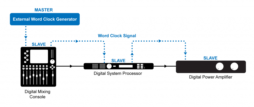
External word clock synchronization is typically accomplished using low impedance coaxial cable with BNC connectors. If your word clock generator has several outputs, you can connect each device directly to the clock master as shown in Figure 5.27. Otherwise you can connect the devices up in sequence from a single word clock output of your clock master shown in Figure 5.28.


If you don’t have a dedicated word clock generator, you could choose one of the digital audio devices in your system to be the word clock master and slave all the other devices in your system to that clock using the external word clock connections as shown in Figure 5.29. The word clock of the device in your system is probably not as stable as a dedicated word clock generator (in that it may have a small amount of jitter), but as long as all the devices are following that clock, you will avoid any errors.

In some cases your equipment may not have external word clock inputs. This is common in less expensive equipment. In that situation you could go with a self-clocking solution where the first device in your signal chain is designated as the word clock master and each device in the signal chain is set to slave to the word clock signal embedded in the audio stream coming from the previous device in the signal chain, as shown in Figure 5.30.

Regardless of the synchronization strategy you use, the goal is to have one word clock master with every other digital device in your system set to slave to the master word clock. If you set this up correctly, you should have no problems maintaining a completely digital signal path through your audio system and benefit from the decreased latency from input to output.