7.2.1.1 Mixing Contexts and Devices
[aside]The fact that digital consoles often follow analog models of control and layout is somewhat of a hot topic. On one hand, this similarity provides some standardization and ease of transition between the two types of consoles. Yet with all of the innovations in user interface technology, you might wonder why these implementations have remained so “old fashioned.” Many people are beginning to use hi-tech UI devices like the iPad along with wireless control protocols like OSC to reinvent the way mixing and audio manipulation is done. While it may take some time for these new techniques to emerge and catch on, the possibilities they provide are both fascinating and seemingly limitless.[/aside]
A mixing console, or mixer, is a device that takes several different audio signals and mixes them together, to be sent to another device in a more consolidated or organized manner. Mixing can be done in a variety of contexts. Mixing during a live performance requires that an audio engineer balance the sounds from a number of sources. Mixing is also done in the sound studio, as the recordings from multiple channels or on multiple tracks are combined.
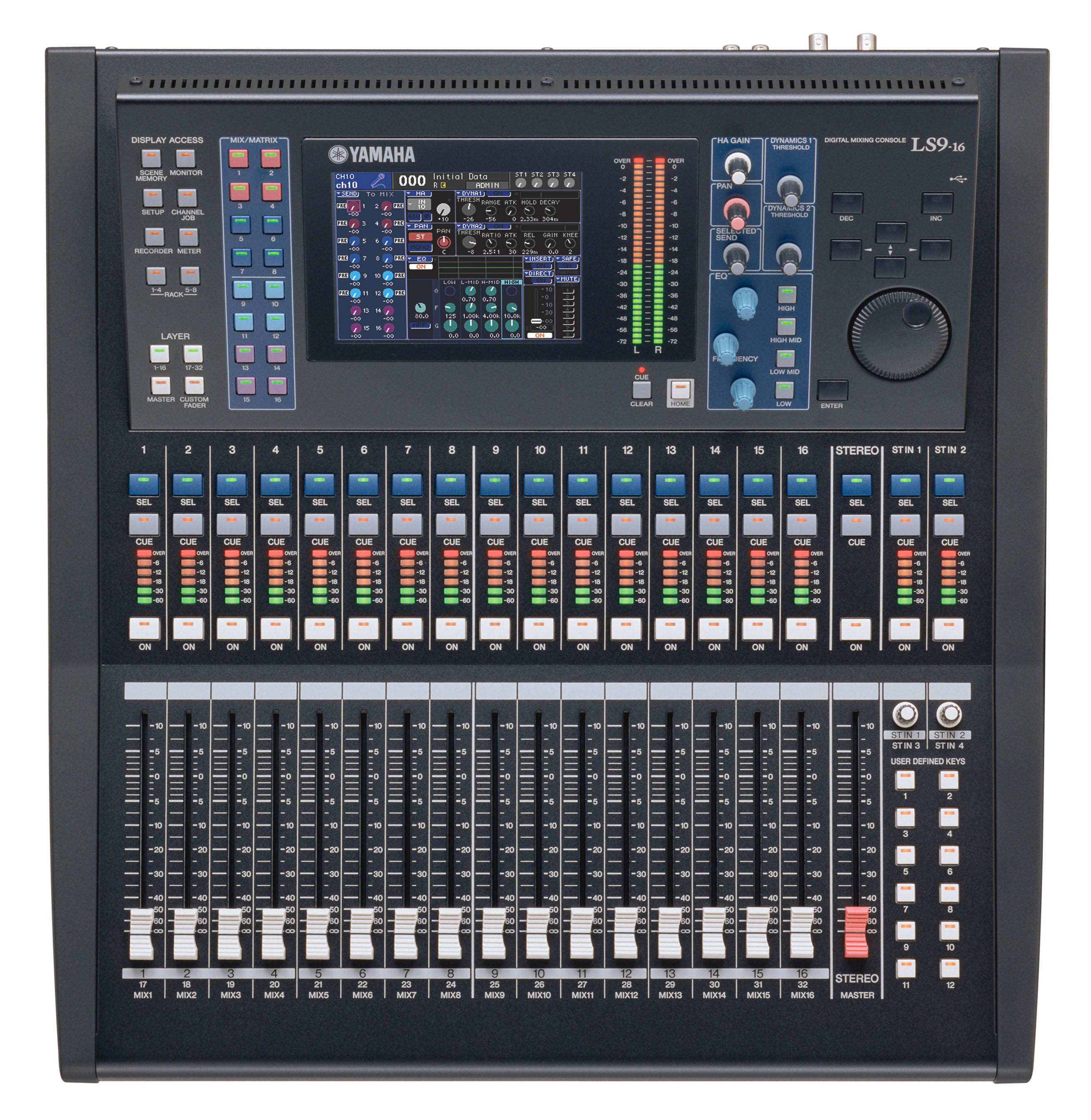
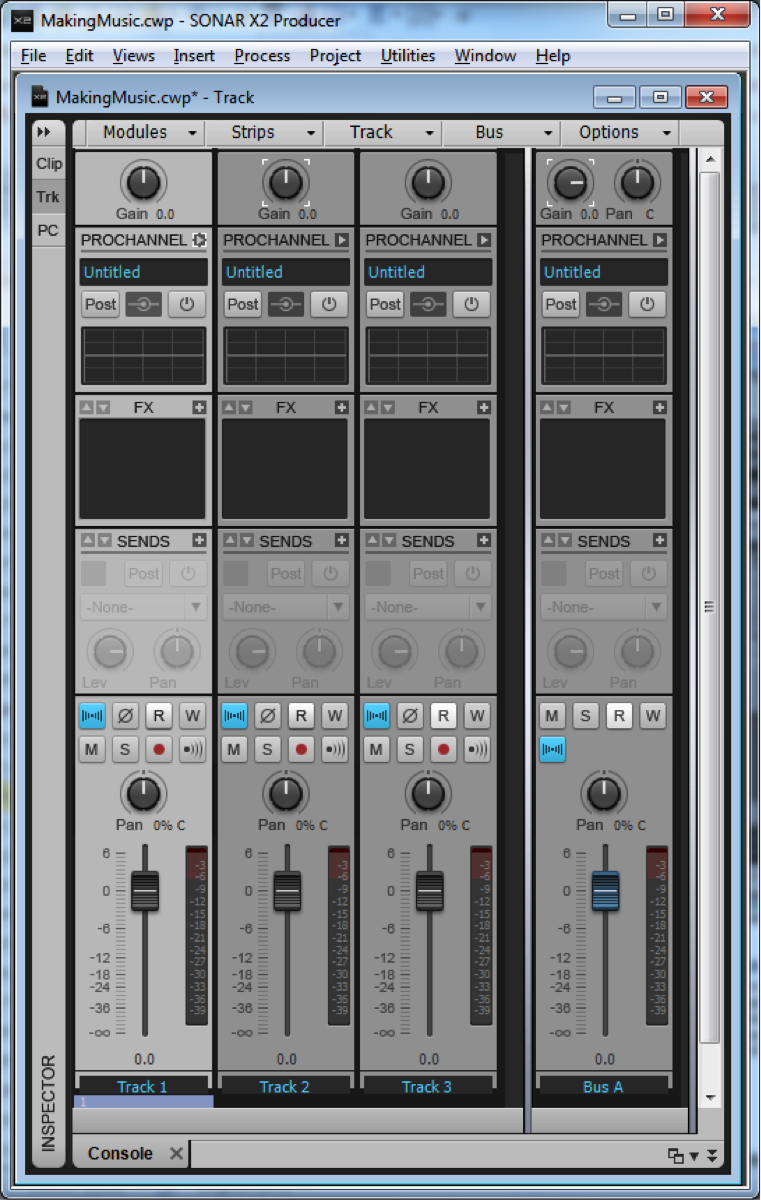
Mixing can also be done with a variety of tools. An audio engineering doing the mixing of a live performance could use a hardware device like the one shown in Figure 7.19, an analog mixing console. Digital mixers have now become more common (Figure 7.20), and as you can see, they look pretty much the same as their analog counterparts. Software mixers, with user interfaces modeled after equivalent hardware, are a standard part of audio processing programs like Pro Tools, Apple Logic, Ableton Live, and Cakewalk Sonar. The mixing view for a software mixer is sometimes called the console view, as is the case with Cakewalk Sonar, pictured in Figure 7.21.

In the following section, we introduce the different components and functions of mixers. Whether a mixer is analog or digital, hardware or software, is not the point. The controls and functions of mixers are generally the same no matter what type you’re dealing with or the context in which you’re doing the mixing. A Max demo on mixing consoles is included in Chapter 8.
7.2.1.2 Inputs and Outputs
The original concept behind a mixer was to take the signals from multiple sources and combine them into a single audio signal that could be sent to a recording device or to an amplification system in a performance space. These so-called “mix down” consoles would have several audio input connections but very few output connections. With the advent of surround sound, distributed sound reinforcement systems, multitrack recorders, and dedicated in-ear monitors, most modern mixing consoles have just as many, if not more, outputs than inputs, allowing the operator to create many different mixes that are delivered to different destinations.
Consider the situation of a recording session of a small rock band. You could easily have more than twenty-four microphones spread out across the drums, guitars, vocalists, etc. Each microphone connects to the mixing console on a separate audio input port and is fed into an input channel on the mixing console. Each channel has a set of controls that allows you to optimize and adjust the volume level and frequency response of the signal and send that signal to several output channels on the mixing console. Each output channel represents a different mix of the signals from the various microphones. The main mix output channel likely contains a mix of all the different microphones and is sent to a pair (or more) of monitor loudspeakers in the control room for the recording engineer and other participants to listen to the performance from the band. This main mix may also represent the artistic arrangement of the various inputs, decided upon by the engineer, producer, and band members, eventually intended for mixed-down distribution as a stereo or surround master audio file. Each performer in the band is also often fed a separate auxiliary output mix into her headphones. Each auxiliary mix contains a custom blend of the various instruments that each musician needs to hear in order to play her part in time and in tune with the rest of the band. Ideally, the actual recording is not a mix at all. Instead, each input channel has a direct output connection that sends the microphone signal into a dedicated channel on a multitrack recording device, which in the digital age is often a dedicated computer DAW. This way the raw, isolated performances are captured in their original state, and the artistic manipulation of the signals can be accomplished incrementally and non-destructively during the mixing process.
7.2.1.3 Channel Strips
[wpfilebase tag=file id=154 tpl=supplement /]
Configuring all the knobs, buttons, and faders on a suitably sized mixing console makes all of the above functions possible. When you see a large mixing console like the one pictured in Figure 7.19, you might feel intimidated by all the knobs and buttons. It’s important to realize that most of the controls are simply duplicates. Each input channel is represented by a vertical column, or channel strip, of controls as shown in Figure 7.22.
It’s good to realize that the audio signal typically travels through the channel strip and its various controls from top to bottom. This makes it easy to visualize the audio signal path and understand how and when the audio signal is being affected. For example, you’ll usually find the preamp gain control at the top of the channel strip, as this is the first circuit the audio signal encounters, while the level fader at the bottom is the last component the signal hits as it leaves the channel strip to be mixed with the rest of the individual signals.

7.2.1.4 Input Connectors
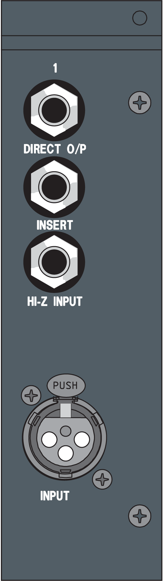
Each input channel has at least one input connector, as shown in Figure 7.23. Typically this is an XLR connector. Some mixing consoles also have a ¼” TRS connector on each input channel. The idea for including both is to use the XLR connector for microphone signals and the ¼” connector for line level or high impedance instrument signals, though you can’t use both at the same time. In some cases, both connectors feed into the same input circuitry, allowing you to use the XLR connector for line level signals as well as microphone signals. This is often desirable, and whenever possible you should use the XLR connector rather than the ¼” because of its benefits such as a locking connection. In some cases, the ¼” connector feeds into the channel strip on a separate path from the XLR connector, bypassing the microphone preamplifier or encountering a -20 dB attenuation before entering the preamplifier. In this situation, running a line level signal through the XLR connector may result in a clipped signal because there is no gain adjustment to compensate for the increased voltage level of the line level signal. Each mixing console implements these connectors differently, so you’ll need to read the manual to find out the specific configuration and input specifications for your mixing console.
7.2.1.5 Gain Section
The gain section of the channel strip includes several controls. The most important is the gain knob. Sometimes labeled trim, this knob controls the preamplifier for the input channel. The preamplifier is an electrical circuit that can amplify the incoming audio signal to the optimal line level voltage suitable for use within the rest of the console. The preamplifier is often designed for high quality and very low noise so that it can boost the audio signal without adding a lot of noise or distortion. Because of the sheer number of electrical circuits an audio signal can pass through in a mixing console, the signal can pick up a lot of noise as it travels around in the console. The best way to minimize the effects of this noise is to increase the signal-to-noise ratio from the very start. Since the preamplifier is able to increase the level of the incoming audio signal without increasing the noise level in the console, you can use the preamplifier to increase the ratio between the noise floor of the mixing console and the level of your audio signal. Therefore, the goal of the gain knob is to achieve the highest value possible without clipping the signal. (Chapter 8 has more details on gain setting.)

This is the only place in the console (and likely your entire sound system) where you can increase the level of the signal without also increasing the noise. Thus, you should get all the gain you can at this stage. You can always turn the level down later in the signal chain. Don’t succumb to the temptation to turn down the mixing console preamplifier as a convenient way to fix problems caused downstream by power amplifiers and loudspeakers that are too powerful or too sensitive for your application. Also, you should not turn down the preamplifier in an effort to get all the channel faders to line up in a straight row. These are excellent ways to create a noisy sound system because you’re decreasing the signal-to-noise ratio for the incoming audio signal. Once you’ve set that gain knob to the highest level you can without clipping the signal, the only reason you should ever touch it again is if the signal coming in to the console gets louder and starts clipping the input.
If you’re feeding a line level signal into the channel, you might find that you’re clipping the signal even though the gain knob is turned all the way down. Most mixing consoles have a pad button next to the gain knob. This pad button (sometimes labeled “-20 dB”, “Line”, “range” or “Mic/Line”) attenuates the signal by -20 dB, which should allow you to find a setting on your gain knob that doesn’t clip. Using the pad button shouldn’t necessarily be something you do automatically when using line level signals, as you’re essentially undoing 20 dB of built-in signal-to-noise ratio. Don’t use it unless you have to. Be aware that sometimes this button also serves to reroute the input signal using the ¼” input instead of the XLR. On some consoles that have both ¼” and XLR inputs yet don’t have a pad button, it’s because the -20 dB attenuation is already built in to the signal chain of the ¼” input. These are all factors to consider when deciding how to connect your equipment to the mixing console. (A Max demo in Chapter 8 provides more information on gain setting.)
Another button you’ll commonly find next to the gain knob is labeled Ø. This is probably the most misunderstood button in the world of sound. Unfortunately, the mixing console manufacturers contribute to the confusion by labeling this button with the universal symbol for phase. In reality, this button has nothing to do with phase. This is a polarity button. Pressing this button simply inverts the polarity of your signal.
The badly-chosen symbol for the polarity button is inherited from the general confusion among sound practitioners about the difference between phase and polarity. It’s true that for pure sine waves, a 180-degree phase shift is essentially identical to a polarity inversion. But that’s the only case where these two concepts intersect. In the real world of sound, pure sine waves are hardly ever encountered. For complex sounds that you deal with in practice, phase and polarity are fundamentally different. Phase changes in complex sounds are typically the result of an offset in time. The phase changes as a result of timing offsets are not consistent across the frequency spectrum. A shift in time that would create a 180-degree phase offset for a 1 kHz sound would create a 360-degree phase offset for 2 kHz. This inconsistent phase shift across the frequency spectrum for complex sounds is the cause of comb filtering when two identical sounds are mixed together with an offset in time. Given that a mixing console is all about mixing sounds, it is very easy to cause comb filtering when mixing two microphones that are picking up the same sound at two different distances resulting in a time offset. If you think the button in question adjusts the phase of your signal (as the symbol on the button suggests), you might come to the conclusion that pressing this button manipulates the timing of your signal and compensate for comb filter problems. Nothing could be further from the truth. In a comb filter situation, pressing the polarity button for one of the two signals in question simply convert all cancelled frequencies into frequencies that reinforce each other. All the frequencies that were reinforcing each other will now cancel out. Once you’ve pressed this button, you still have a comb filter. It’s just an inverted comb filter. When you encounter two channels on your console that cause a comb filter when mixed together, a better strategy is to simply eliminate one of the two signals. After all, if these two signals are identical enough to cause a comb filter, you don’t really need both of them in your mix, do you? Simply ducking the fader on one of the two channels will solve your comb filter problem much more efficiently, and certainly more so than using the polarity button.
If this button has nothing to do with phase, what reason could you possibly have to push it? There are many situations where you might run into a polarity problem with one of your input signals. The most common is the dreaded “pin 3 hot” problem. In Chapter 1, we talked about the pinout for an XLR connector. We said that pin 2 carries the positive or “hot” signal and pin 3 carries the negative or “cold” signal. This is a standard from the Audio Engineering Society that was ratified in 1982. Prior to that, each manufacturer did things differently. Some used pin 2 as hot and some used pin 3 as hot. This isn’t really a problem until you start mixing and matching equipment from different manufacturers. Let’s assume your microphone uses pin 2 as hot, but your mixing console uses pin 3 as hot. In that situation, the polarity of the signal coming into the mixing console is inverted. Now if you connect another microphone to a second channel on your mixing console and that microphone also uses pin 3 as hot, you have two signals in your mixing console that are running in opposite polarity. In these situations, having a polarity button on each channel strip is an easy way to solve this problem. Despite the pin 2 hot standard being now thirty years old, there are still some manufacturers making pin-3-hot equipment.
Even if all your equipment is running pin 2 hot, you could still have a polarity inversion happening in your cables. If one end of your cable is accidentally wired up incorrectly (which happens more often than you might think), you could have a polarity inversion when you use that cable. You could take the time to re-solder that connector (which you should ultimately take care of), but if time is short or the cable is hard to get to, you could simply press the polarity button on the mixing console and instantly solve the problem.
There could be artistic reasons you would want to press the polarity button. Consider the situation where you are trying to capture the sound of a drum. If you put the microphone over the top of the drum, when the drum is hit, the diaphragm of the microphone pulls down towards the drum. When this signal passes through your mixing console on to your loudspeakers, the loudspeaker driver also pulls back away from you. Wouldn’t it make more sense for the loudspeaker driver to jump out towards you when the drum is hit? To solve this problem you could go back to the drummer and move the microphone so it sits underneath the drum, or you could save yourself the trip and just press the polarity button. The audible difference here might be subtle, but when you put enough subtle differences together, you can often get a significant difference in audio quality.
Another control commonly found in the gain section is the phantom power button. Phantom power is a 48-volt electrical signal that is sent down the shield of the microphone cable to power condenser microphones. In our example, there is a dedicated 48-volt phantom power button for each input channel strip. In some consoles, there’s a global phantom power button that turns on phantom power for all inputs.
The last control that is commonly found in the gain section of the console is a high-pass filter. Pressing this button filters out frequencies below the cutoff frequency for the filter. Sometimes this button has a fixed cutoff frequency of 80Hz, 100Hz, or 125Hz. Some mixing consoles give you a knob along with the button that allows you to set a custom cutoff frequency for the high pass filter. When working with microphones, it’s very easy to pick up unwanted sounds that have nothing to do with the sound you’re trying to capture. Footsteps, pops, wind, and handling noise from people touching and moving the microphone are all examples of unwanted sounds that can show up in your microphone. The majority of these sounds fall in very low frequencies. Most musical instruments and voices do not generate frequencies below 125 Hz, so you can safely use a high-pass to filter out frequencies lower than that. Engaging this filter removes most of these unwanted sounds before they enter the signal chain in your system without affecting the good sounds you’re trying to capture. Still, all filters have an effect on the phase of the frequencies surrounding the cutoff frequency, and they can introduce a small amount of additional noise into the signal. For this reason, you should leave the high-pass filter disengaged unless you need it.
7.2.1.6 Insert
Next to the channel input connectors typically there is a set of insert connections. Insert connections consist of an output and input that allow you to connect some kind of external processing device in line with the signal chain in the channel strip. The insert output takes the audio signal from the channel directly after it exits the preamplifier, though some consoles let you choose at what point in the signal path the insert path lies. Thinking back to the top-down signal flow, the insert connections are essentially “inserting” an extra component at that point on the channel strip. In this case, the component isn’t built into the channel strip like the EQ or pan controls. Rather, the device is external and can be whatever the engineer wishes to use. If, for example, you want to compress that dynamics of the audio on input channel 1, you can connect the insert output from channel 1 to the input of an external compressor. Then the output of the compressor can be connected to the insert input on channel 1 of the mixing console. The compressed signal is then fed back into the channel strip and continues down the rest of the signal chain for channel 1. If nothing is connected to the insert ports, it is bypassed and the signal is fed directly through the internal signal chain for that input channel. When you connect a cable to the insert output, the signal is almost always automatically rerouted away from the channel strip. You’ll need to feed something back into the insert input in order to continue using that channel strip on the mixing console.
There are two different connection designs for inserts on a mixing console. The ideal design is to have a separate ¼” or XLR connection for both the insert output and input. This allows you to use standard patch cables to connect the external processing equipment, and may also employ a balanced audio signal. If the company making the mixing console needs to save space or cut down on the cost of the console, they might decide to integrate both the insert output and input on a single ¼” TRS connector. In this case, the input and output are handled as unbalanced signals using the tip for one signal, the ring for the other signal, and a shared neutral on the sleeve. There is no standard for whether the input or output is carried on the tip vs. the ring. To use this kind of insert requires a special cable. This cable has three connectors. On one end is a ¼” TRS connector. This connector has two cables coming out of the end. One cable feeds an XLR male or a ¼” TS connector for the insert output and a XLR female or a ¼” TS connector for the insert input.
7.2.1.7 Equalizer Section
After the gain section of the channel strip, the next section your audio signal encounters is the equalizer section (EQ) shown in Figure 7.25. The number of controls you see in this section of the channel strip varies greatly across the various models of mixing consoles. Very basic consoles may not include an EQ section at all. Generally speaking, the more money you pay for the console, the more knobs and buttons you find in the EQ section. We discussed the equalization process in depth in Chapter 7.
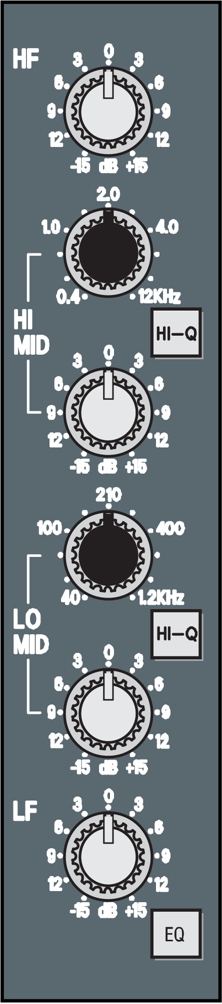
Even the simplest of mixing consoles typically has two channels of EQ in each channel strip. These are usually a high shelf and a low shelf filter. These simple EQ sections consist of two knobs. One controls the gain for the high shelf and the other for the low shelf. The shelving frequency is a fixed value. If you pay a little more for your mixing console, you can get a third filter – a mid-frequency peak-notch filter. Again, the single knob is a gain knob with a fixed center frequency and bandwidth.
The next controllable parameter you’ll get with a nicer console is a frequency knob. Sometimes only the mid-frequency notch filter gets the extra variable center frequency knob, but the high and low shelf filters may get a variable filter frequency using a second knob as well. With this additional control, you now have a semi-parametric filter. If you are given a third knob to control the filter Q or Bandwidth, the filter becomes fully parametric. From there you simply get more bands of fully parametric filters per channel strip as the cost of the console increases.
Depending on your needs, you may not require five bands of EQ per channel strip. The option that is absolutely worth paying for is an EQ bypass button. This button routes the audio signal in the channel around the EQ circuit. This way, the audio signal doesn’t have to be processed by the EQ if you don’t need any adjustments to the frequency response of the signal. Routing around the EQ solves two potential problems. The first is the problem of inheriting someone else’s solution. There are a lot of knobs on a mixing console, and they aren’t always reset when you start working on a new project. If the EQ settings from a previous project are still dialed in, you could be inheriting a frequency adjustment that’s not appropriate for your project. Having an EQ bypass button is a quick way to turn off all the EQ circuits so you’re starting with a clean slate. The bypass button can also help you quickly do an A/B comparison without having to readjust all of the filter controls. The second problem is related to noise floor. Even if you have all the EQ gain knobs flattened out (no boost or cut), your signal is still passing though all those circuits and potentially collecting some noise along the way. Bypassing the EQ allows you to avoid that unnecessary noise.
7.2.1.8 Auxiliaries
The Auxiliary controls in the channel strip are shown in Figure 7.26. Each auxiliary send knob represents an additional physical audio path/output on the mixing console. As you increase the value of an auxiliary send knob, you’re setting a certain level of that channel’s signal to be sent into that auxiliary bus. As each channel is added into the bus to some degree, a mix of those sounds is created and sent to a physical audio output connected to that bus. You can liken the function of the auxiliary busses to an actual bus transportation system. Each bus, or bus line, travels to a unique destination, and the send knob controls how much of that signal is getting on the bus to go there. In most cases, the mixing console will also have a master volume control to further adjust the combined signal for each auxiliary output. This master control can be a fader or a knob and is usually located in the central control section of the mixing console.
An auxiliary is used whenever you need to send a unique mix of the various audio signals in the console to a specific device or person. For example, when you record a band, the lead singer wears headphones to hear the rest of the band as well as her own voice. Perhaps the guitar is the most important instrument for the singer to hear because the guitar contains the information about the right pitch the singer needs to use with her voice. In this situation, you would connect her headphones to a cable that is fed from an auxiliary output, which we’ll call “Aux 1,” on the mixing console. You might dial in a bit of sound to Aux 1 across each input channel of the mixing console, but on the channels containing the guitar and the singer’s own vocals the Aux 1 controls would be set to a higher value so they’re louder in the mix being sent to the singer’s headphones.
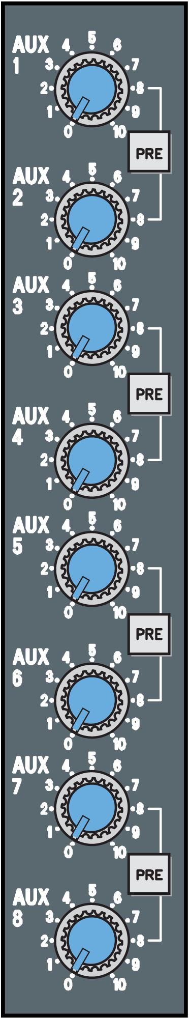
The auxiliary send knobs on an input channel strip come in two configurations. Pre-Fader aux sends a signal level into the aux bus independently of the position of the channel fader. In our example of the singer in the band, a pre-fade aux would be desirable because once you’ve dialed in an aux mix that works for the singer, you don’t want that mix changing every time you adjust the channel fader. When you adjust the channel fader, it’s in response to the main mix that is heard in the control room, which has no bearing on what the singer needs to hear.
The other configuration for an aux send is Post-Fader. In this case, dialing in the level on the aux send knob represents a level relative to the fader position for that input channel. So when the main mix is changed via the fader, the level in that aux send is changed as well. This is particularly useful when you’re using an aux bus for some kind of effect processing. In our same recording session example, you might want to add some reverberation to the mix. Instead of inserting a separate reverb processor on each input channel, requiring multiple processors, it’s much simpler to connect an aux output on the mixing console to the input of a single reverb processor. The output of the reverb processor then comes back into an unused input channel on the mixing console. This way, you can use the aux sends to dial in the desired amount of reverb for each input channel. The reverb processor then returns a reverberant mix of all of the sounds that gets added into the main mix. Once you get a good balance of reverb dialed in on an aux send for a particular input channel, you don’t want that balance to change. If the aux send to the reverb is pre-fader, when the fader is used to adjust the channel level within the main mix, the reverb level remains the same, disrupting the balance you achieve. Instead, when you turn up or down the channel fader, the level of the reverb should also increase or decrease respectively so the balance between the dry and the reverberant (wet) sound stays consistent. Using a post-fader aux send accomplishes this goal.
Some mixing consoles give you a switch to change the behavior of an aux bus between pre-fader and post-fader, while in other consoles this behavior may be fixed. Sometimes this switch is located next to the aux master volume control, and changes the pre-fader or post-fader mode for all of the channel aux sends that feed into that bus. More expensive consoles allow you to select pre- or post-fader behavior in a channel-specific way. In other words, each individual aux send dial on an input channel strip has its own pre- or post-fade button. With this flexibility Aux 1 can be set as a pre-fade aux for input channel 1 and a post-fade aux for input channel 2.
7.2.1.9 Fader and Routing Section
The fader and routing section shown in Figure 7.27 is where you usually spend most of your time working with the console in an iterative fashion during the artistic process of mixing. The fader is a vertical slider control that adjusts the level of the audio signal sent to the various mixes you’ve routed on that channel. There are two common fader lengths: 60 mm and 100 mm. The 100 mm faders give your fingers greater range and control and are easier to work with. The fader is primarily an attenuator. It reduces the level of the signal on the channel. Once you’ve set the optimal level for the incoming signal with the preamplifier, you use the fader to reduce that level to something that fits well in the mix with the other sounds. The fader is a very low-noise circuit, so you can really set it to any level without having adverse effects on signal-to-noise ratio. One way to think about it is that the preamplifier is where the science happens; the fader is where the art happens. The fader can reduce the signal level all the way to nothing (−∞ or –inf), but typically has only five to ten dB on the amplification end of the level adjustment scale. When the fader is set to 0 dB, also referred to as unity, the audio signal passes through with no change in level. You should set the fader level to whatever sounds best, and don’t be afraid to move it around as the levels change over time.
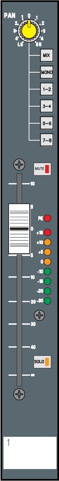
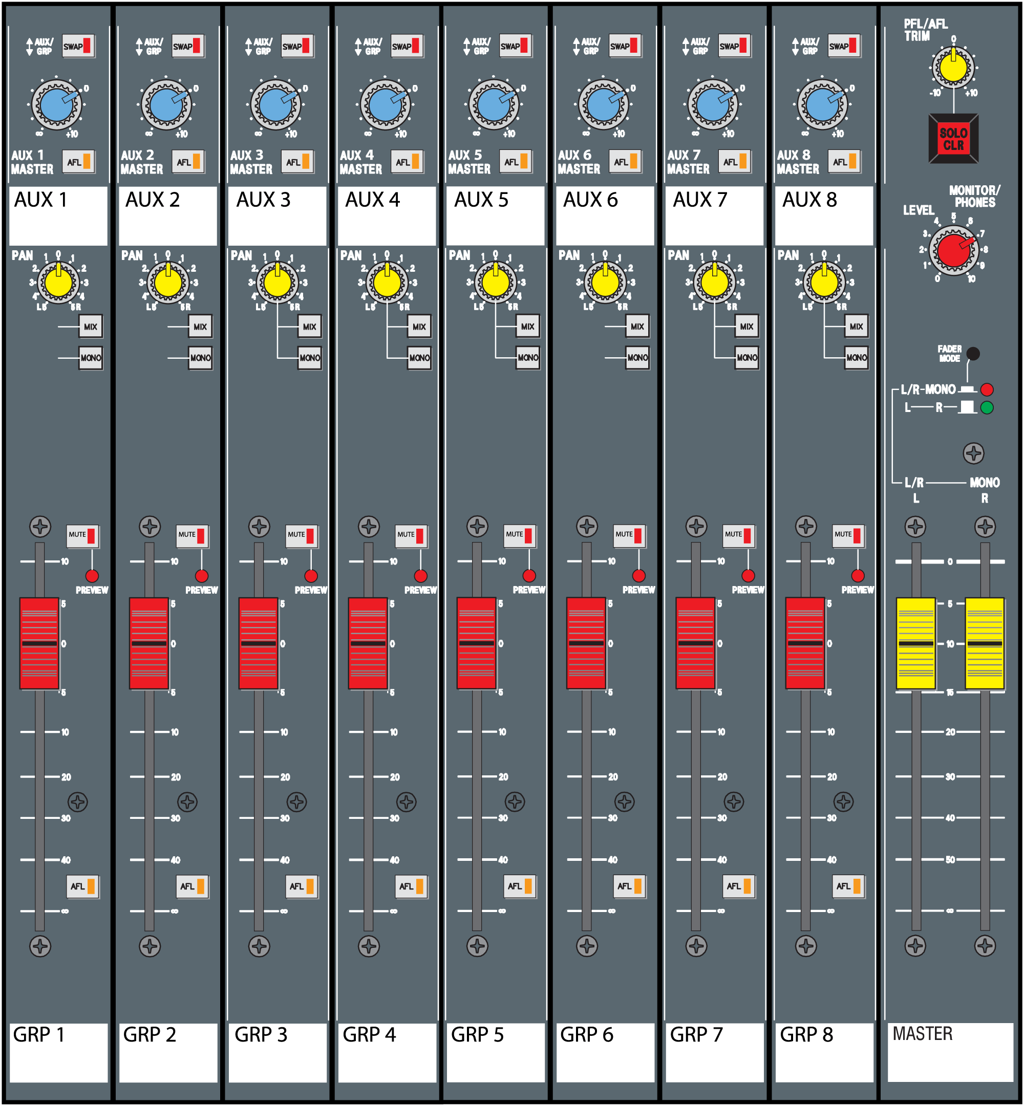
Near the fader there is usually a set of signal routing buttons. These buttons route the audio signal at a fixed level relative to the fader position to various output channels on the mixing console. There is almost always a main left and right stereo output (labeled “MIX” in Figure 7.27), and sometimes a mono or center output. Additionally, you may also be able to route the signal to one or more group outputs or subgroup mixes. A subgroup (sometimes, as with auxiliaries, also called a bus) represents a mixing channel where input signals can be grouped together under a master volume control before being passed on to the main stereo or mono output, as shown in Figure 7.28. An example of subgroup routing would be to route all the drum microphones to a subgroup so you can mix the overall level of the drums in the main mix using only one fader. A group is essentially the same thing, except it also has a dedicated physical output channel on the mixing console. The terms bus, group, and subgroup are often used interchangeably. Group busses are almost always post fader, and unlike auxiliary busses don’t have variable sends – it’s all or nothing. Group routing buttons are often linked in stereo pairs, where you can use the pan knob to pan the signal between the paired groups, in addition to panning between the main stereo left and right bus.
Also near the fader you usually have a mute button. The mute button mimics the behavior of pulling the input fader all the way down. In this case, pre-fade auxiliaries would continue to function. The mute button comes in handy when you want to stop hearing a particular signal in the main mix, but you don’t want to lose the level you have set on the fader or lose any auxiliary functionality, like signal being sent a headphone or monitor mix. Instead of a mute button, you may see an on/off button. This button shuts down the entire channel strip. In that situation, all signals stop on the channel, including groups, auxiliaries, and direct outs. Just to confuse you, manufacturers may use the terms mute and on/off interchangeably so in some cases, a mute button may behave like an on/off button and vice versa. Check the user manual for the mixing console to find out the exact function of your button.
Next to the fader there is typically a pre-fade listen (PFL) or a solo button. Pressing the PFL button routes the signal in that channel strip to a set of headphones or studio monitor outputs. Since it is pre-fade, you can hear the signal in your headphones even if the fader is down or the mute button is pressed. This is useful when you want to preview the sound on that channel before you allow it to be heard via your main or group outputs. If you have a solo button, when pressed it will also mute all the other channels, allowing you to hear only the solo-enabled channels. Solo is found in recording studio consoles or audio recording software. Sometimes the terms PFL and solo are used interchangeably so, again, check the user manual for your mixing console to be sure of the function for this button.
Similar to PFL is after-fade listen (AFL). AFL is found on output faders allowing you to preview in your headphones the signal that is passing through a subgroup, group, aux, or main output. The after-fade feature is important because it allows you to hear exactly what is passing through the output, including the level of the fader. For example, if a musician says that he can’t hear a given instrument in his monitor, you can use the AFL feature for the aux that feeds that monitor to see if the instrument can be heard. If you can hear it in your headphones, then you know that the aux is functioning properly. In this case, you may need to adjust the mix in that aux to allow the desired instrument to be heard more easily. If you can’t hear the desired instrument in your headphones, then you know that you have a routing problem in the mixing console that’s preventing the signal from sending out from that aux output.
Depending on the type of mixing console you’re using, you may also have some sort of PPM (Peak Program Meter) near the fader. In some cases, this will be at the top of the console on a meter bridge. Cheaper consoles will just give you two LED indicators, one for when audio signal is present and another for when the signal clips. More expensive consoles will give you high-resolution PPMs with several different level indicators. A PPM is more commonly found in digital systems, but is also used in analog equipment. A PPM is typically a long column of several LED indicators in three different colors, as shown in Figure 7.29. One color represents signal levels below the nominal operating level, another color represents signals at or above nominal level, and the third color (usually red) represents a signal that is clipping or very near to clipping. A PPM responds very quickly to the audio signal. Therefore, a PPM is very useful for measuring peak values in an audio signal. If you’re trying to find the right position for a preamplifier, a PPM will show you exactly when the signal clips. Most meters in audio software are programmed to behave like a PPM.
