7.1.10.1 Amplitude Adjustment and Normalization
One of the most straightforward types of audio processing is amplitude adjustment – something as simple as turning up or down a volume control. In the analog world, a change of volume is achieved by changing the voltage of the audio signal. In the digital world, it’s achieved by adding to or subtracting from the sample values in the audio stream – just simple arithmetic.
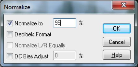
An important form of amplitude processing is normalization, which entails increasing the amplitude of the entire signal by a uniform proportion. Normalizers achieve this by allowing you to specify the maximum level you want for the signal, in percentages or dB, and increasing all of the samples’ amplitudes by an identical proportion such that the loudest existing sample is adjusted up or down to the desired level. This is helpful in maximizing the use of available bits in your audio signal, as well as matching amplitude levels across different sounds. Keep in mind that this will increase the level of everything in your audio signal, including the noise floor.
7.1.10.2 Dynamics Compression and Expansion
[wpfilebase tag=file id=141 tpl=supplement /]
Dynamics processing refers to any kind of processing that alters the dynamic range of an audio signal, whether by compressing or expanding it. As explained in Chapter 5, the dynamic range is a measurement of the perceived difference between the loudest and quietest parts of an audio signal. In the case of an audio signal digitized in n bits per sample, the maximum possible dynamic range is computed as the logarithm of the ratio between the loudest and the quietest measurable samples – that is, $$20\log_{10}\left ( \frac{2^{n-1}}{1/2} \right )dB$$. We saw in Chapter 5 that we can estimate the dynamic range as 6n dB. For example, the maximum possible dynamic range of a 16-bit audio signal is about 96 dB, while that of an 8-bit audio signal is about 48 dB.
The value of $$20\log_{10}\left ( \frac{2^{n-1}}{1/2} \right )dB$$ gives you an upper limit on the dynamic range of a digital audio signal, but a particular signal may not occupy that full range. You might have a signal that doesn’t have much difference between the loudest and quietest parts, like a conversation between two people speaking at about the same level. On the other hand, you might have at a recording of a Rachmaninoff symphony with a very wide dynamic range. Or you might be preparing a background sound ambience for a live production. In the final analysis, you may find that you want to alter the dynamic range to better fit the purposes of the recording or live performance. For example, if you want the sound to be less obtrusive, you may want to compress the dynamic range so that there isn’t such a jarring effect from a sudden difference between a quiet and a loud part.
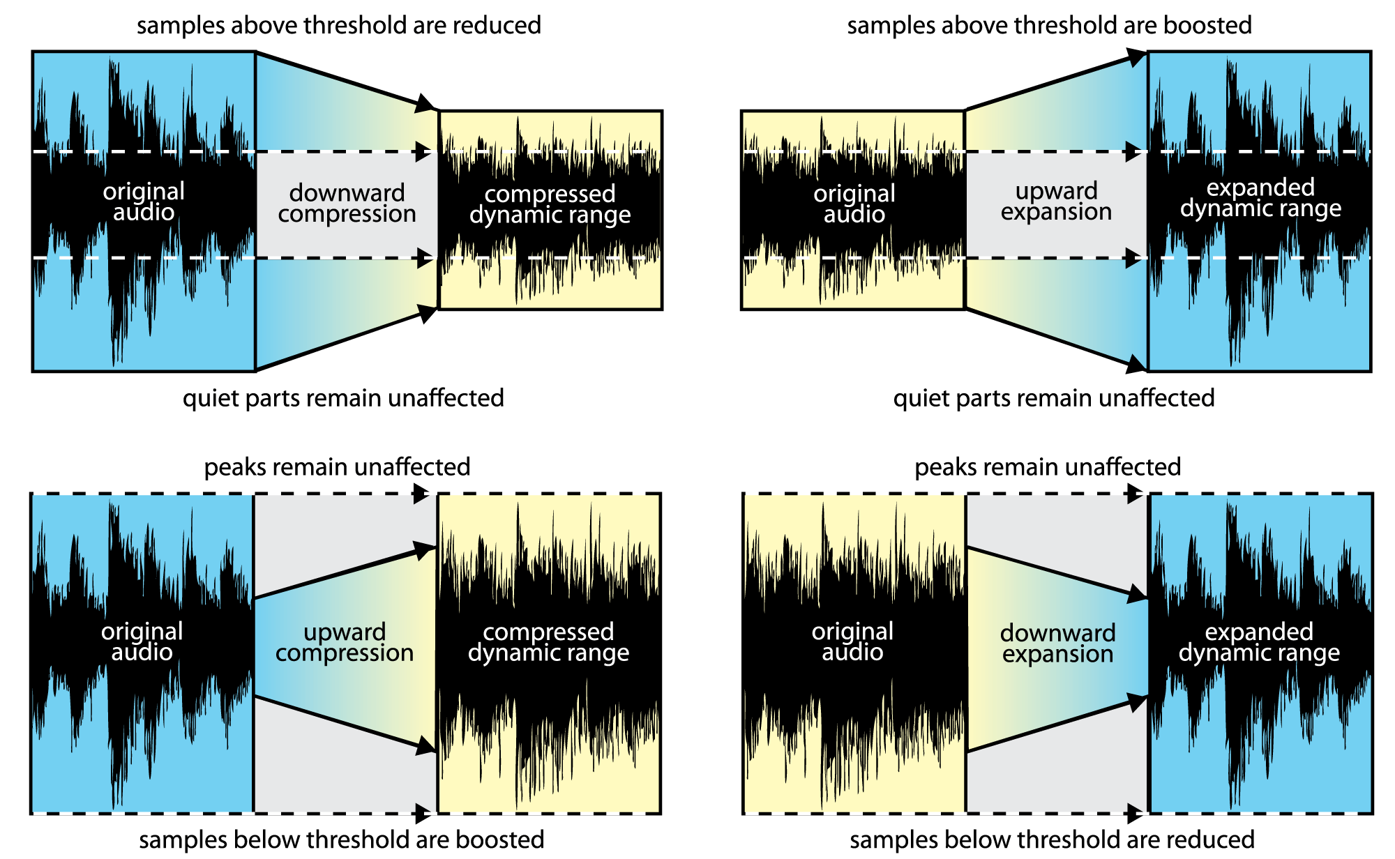
In dynamics processing, the two general possibilities are compression and expansion, each of which can be done in the upwards or downwards direction (Figure 7.13). Generally, compression attenuates the higher amplitudes and boosts the lower ones, the result of which is less difference in level between the loud and quiet parts, reducing the dynamic range. Expansion generally boosts the high amplitudes and attenuates the lower ones, resulting in an increase in dynamic range. To be precise:
- Downward compression attenuates signals that are above a given threshold, not changing signals below the threshold. This reduces the dynamic range.
- Upward compression boosts signals that are below a given threshold, not changing signals above the threshold. This reduces the dynamic range.
- Downward expansion attenuates signals that are below a given threshold, not changing signals above the threshold. This increases the dynamic range.
- Upward expansion boosts signals that are above a given threshold, not changing signals below the threshold. This increases the dynamic range.
The common parameters that can be set in dynamics processing are the threshold, attack time, and release time. The threshold is an amplitude limit on the input signal that triggers compression or expansion. (The same threshold triggers the deactivation of compression or expansion when it is passed in the other direction.) The attack time is the amount of time allotted for the total amplitude increase or reduction to be achieved after compression or expansion is triggered. The release time is the amount of time allotted for the dynamics processing to be “turned off,” reaching a level where a boost or attenuation is no longer being applied to the input signal.
Adobe Audition has a dynamics processor with a large amount of control. Most dynamics processor’s controls are simpler than this – allowing only compression, for example, with the threshold setting applying only to downward compression. Audition’s processor allows settings for compression and expansion and has a graphical view, and thus it’s a good one to illustrate all of the dynamics possibilities.
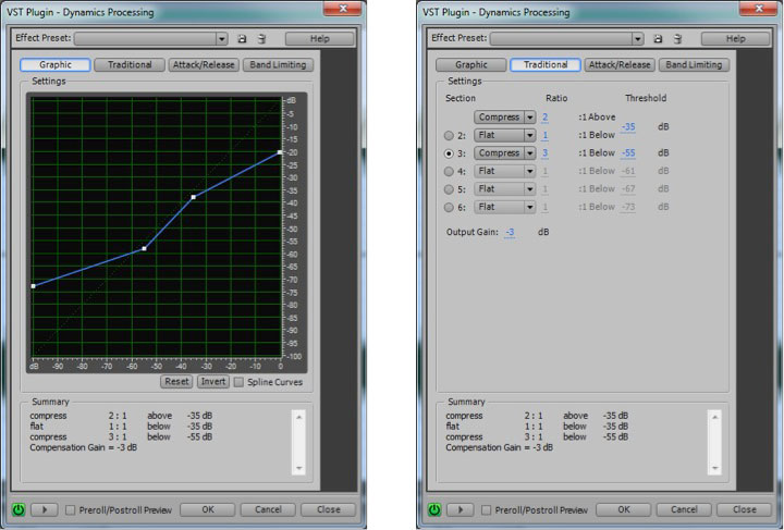
Figure 7.14 shows two views of Audition’s dynamics processor, the graphic and the traditional, with settings for downward and upward compression. The two views give the same information but in a different form.
In the graphic view, the unprocessed input signal is on the horizontal axis, and the processed input signal is on the vertical axis. The traditional view shows that anything above -35 dBFS should be compressed at a 2:1 ratio. This means that the level of the signal above -35 dBFS should be reduced by ½ . Notice that in the graphical view, the slope of the portion of the line above an input value of -35 dBFS is ½. This slope gives the same information as the 2:1 setting in the traditional view. On the other hand, the 3:1 ratio associated with the -55 dBFS threshold indicates that for any input signal below -55 dBFS, the difference between the signal and -55 dBFS should be reduced to 1/3 the original amount. When either threshold is passed (-35 or -55 dBFS), the attack time (given on a separate panel not shown) determines how long the compressor takes to achieve its target attenuation or boost. When the input signal moves back between the values of -35 dBFS and -55 dBFS, the release time determines how long it takes for the processor to stop applying the compression.
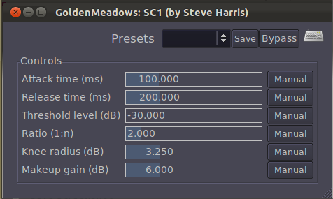
A simpler compressor – one of the ARDOUR LADSPA plug-ins, is shown in Figure 7.15. In addition to attack, release, threshold, and ratio controls, this compressor has knee radius and makeup gain settings. The knee radius allows you to shape the attack of the compression to something other than linear, giving a potentially smoother transition when it kicks in. The makeup gain setting (often called simply gain) allows you to boost the entire output signal after all other processing has been applied.
7.1.10.3 Limiting and Gating
[aside]A limiter could be thought of as a compressor with a compression ratio of infinity to 1. See the next section on dynamics compression.[/aside]
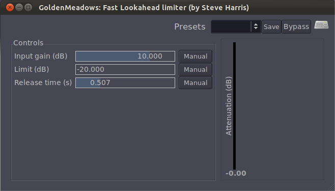
A limiter is a tool that prevents the amplitude of a signal from going over a given level. Limiters are often applied on the master bus, usually post-fader. Figure 7.16 shows the LADSPA Fast Lookahead Limiter plug-in. The input gain control allows you to increase the input signal before it is checked by the limiter. This limiter looks ahead in the input signal to determine if it is about to go above the limit, in which case the signal is attenuated by the amount necessary to bring it back within the limit. The lookahead allows the attenuation to happen almost instantly, and thus there is no attack time. The release time indicates how long it takes to go back to 0 attenuation when limiting the current signal amplitude is no longer necessary. You can watch this work in real-time by looking at the attenuation slider on the right, which bounces up and down as the limiting is put into effect.
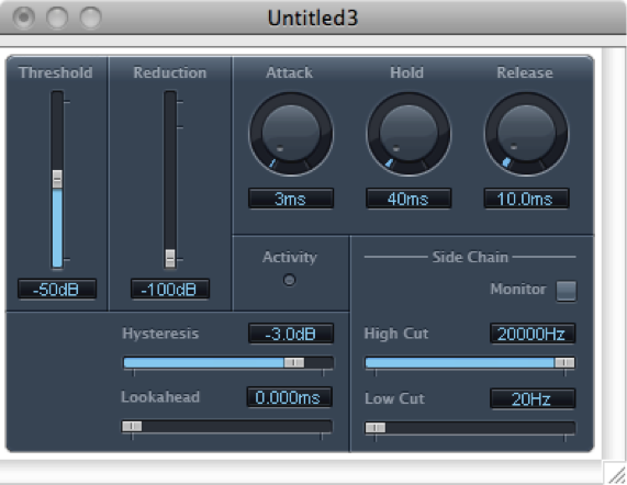
A gate allows an input signal to pass through only if it is above a certain threshold. A hard gate has only a threshold setting, typically a level in dB above or below which the effect is engaged. Other gates allow you to set an attack, hold, and release time to affect the opening, holding, and closing of the gate (Figure 7.18). Gates are sometimes used for drums or other instruments to make their attacks appear sharper and reduce the bleed from other instruments unintentionally captured in that audio signal.
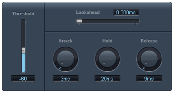
A noise gate is a specially designed gate that is intended to reduce the extraneous noise in a signal. If the noise floor is estimated to be, say, -80 dBFS, then a threshold can be set such that anything quieter than this level is blocked out, effectively transmitted as silence. A hysteresis control on a noise gate indicates that there is a threshold difference between opening and closing the gate. In the noise gate in Figure 7.18, the threshold of -50 dB and the hysteresis setting of -3 dB indicate that the gate closes at -50 dBFS and opens again at -47 dBFS. The side chain controls allow some signal other than the main input signal to determine when the input signal is gated. The side chain signal could cause the gate to close based on the amplitudes of only the high frequencies (high cut) or low frequencies (low cut).
In a practical sense, there is no real difference between a gate and a noise gate. A common misconception is that noise gates can be used to remove noise in a recording. In reality all they can really do is mute or reduce the level of the noise when only the noise is present. Once any part of the signal exceeds the gate threshold, the entire signal is allowed through the gate, including the noise. Still, it can be very effective at clearing up the audio in between words or phrases on a vocal track, or reducing the overall noise floor when you have multiple tracks with active regions but no real signal, perhaps during an instrumental solo.