[wpfilebase tag=file id=45 tpl=supplement /]
Earlier in this chapter, we discussed the fundamentals of synthesizers and the types of controls and processing components you might find built in to their function. In Section 6.1 and in several of the practical exercises and demonstrations, we took you through these components and features one by one. Breaking apart a synthesizer into these individual blocks makes it easier to understand the signal flow and steps behind audio synthesis. In the book, we generally look at software synthesizers in the examples due to their flexibility and availability, most of which come with a full feature set of oscillators, amplifiers, filters, envelopes, and other synthesis objects. Back in the early days of audio synthesis, however, most of this functionality was delegated to separate, dedicated devices. The oscillator device only generated tones. If you also needed a noise signal, that might require you to find a separate piece of hardware. If you wanted to filter the signal, you would need to acquire a separate audio filtering device. These devices were all connected by a myriad of audio patch cables, which could quickly become a complete jumble of wires. The beauty of hardware synthesis was its modularity. There were no strict rules on what wire must plug into what jack. Where a software synth today might have one or two filters at specific locations in the signal path, there was nothing to stop someone back then from connecting a dozen filters in a row if they wanted to and had the available resources. While the modularity and expanse of these setups may seem daunting, it allowed for maximum flexibility and creativity, and could result in some interesting, unique, and possibly unexpected synthesized sounds.
Wouldn’t it be fun to recreate this in the digital world as software? Certainly there are some advantages in this, such as reduced cost, potentially greater flexibility and control, a less cluttered tabletop, not to mention less risk of electrocuting yourself or frying a circuit board. The remainder of this section takes you through the creation of several of these synthesis blocks in MAX, which lends itself quite well to the concept of a creating and using a modular synthesizer. At the end of this example, we’ll see how we can then combine and connect these blocks in any imaginable configuration to possibly create some never-before-heard sounds.
It is assumed that you’re proficient in the basics of MAX. If you’re not familiar with an object we use or discuss, please refer to the MAX help and reference files for that object (Help > Open [ObjectName] Help in the file menu, or Right-click > Open [ObjectName] Help). Every object in MAX has a help file that explains and demonstrates how the object works. Additionally, if you hover the mouse over an inlet or outlet of an object, MAX often shows you a tooltip with information on its format or use. We also try to include helpful comments and hints within the solution itself.
At this point in the chapter, you should be familiar with a good number of these synthesis blocks and how they are utilized. We’ll look at how you might create an audio oscillator, an amplification stage, and an envelope block to control some of our synth parameters. Before we get into the guts of the synth blocks, let’s take a moment to think about how we might want to use these blocks together and consider some of the features of MAX that lend themselves to this modular approach.
It would be ideal to have a single window where you could add blocks and arrange and connect them in any way you want. The blocks themselves would need to have input and outputs for audio and control values. The blocks should have the relevant and necessary controls (knobs, sliders, etc.) and displays. We also don’t necessarily need to see the inner workings of the completed blocks, and because screen space is at a premium, the blocks should be as compact and simply packaged as possible. From a programming point of view, the blocks should be easily copied and pasted, and if we had to change the internal components of one type of block it would be nice if the change reflected across all the other blocks of that type. In this way, if we wanted, say, to add another waveform type to our oscillator blocks later on, and we had already created and connected dozens of oscillator blocks, we wouldn’t have to go through and reprogram each one individually.
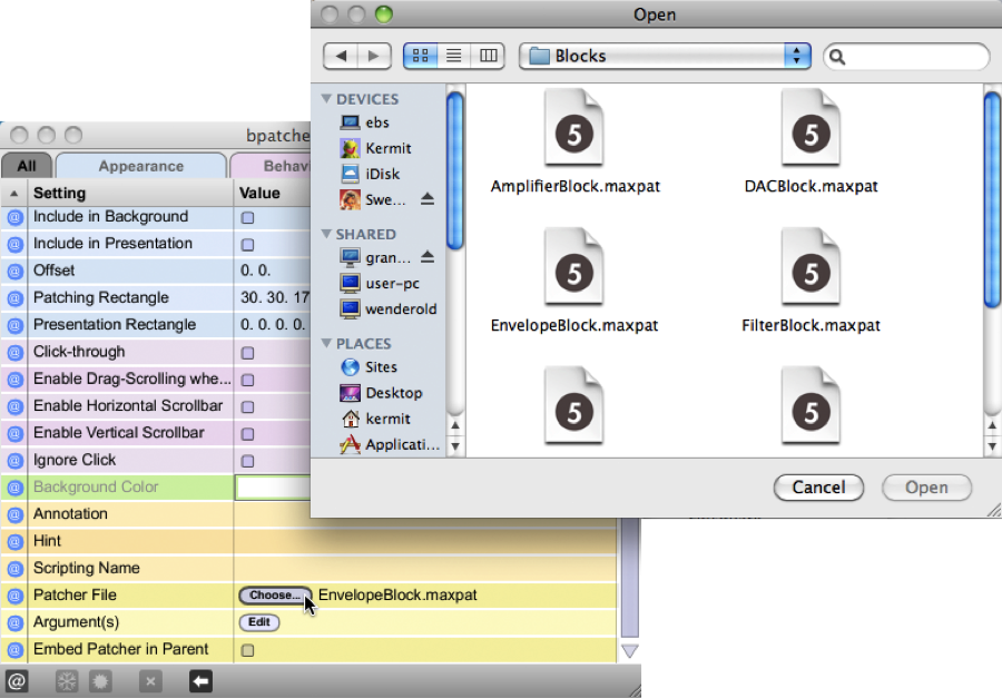
There is an object in MAX called the bpatcher. It is similar in a sense to a typical subpatcher object, in that it provides a means to create multiple elements and a complex functionality inside of one single object. However, where the subpatcher physically contains the additional objects within it, the bpatcher essentially allows you to embed an entire other patcher file inside your current one. It also provides a “window” into the patcher file itself, showing a customizable area of the embedded patcher contents. Additionally, like the subpatcher, the bpatcher allows for connection to and from custom inlets and outlets in the patcher file. Using the bpatcher object, we’re able to create each synth block in its own separate patcher file. We can configure the customizable viewing window to maximize display potential while keeping screen real estate to a minimum. Creating another block is as simple as duplicating the one bpatcher object (no multiple objects to deal with), and as the bpatcher links to the one external file, updating the block file updates all of the instances in our main synthesizer file. To tell a bpatcher which file to link, you open the bpatcher Inspector window (Object > Inspector in the file menu, or select the object and Right-click > Inspector) and click the Choose button on the Patcher File line to browse for the patcher file, as shown in Figure 6.46.
Of course, before we can embed our synth block files, we need to actually create them. Let’s start with the oscillator block as that’s the initial source for our sound synthesis. Figure 6.47 shows you the oscillator block file in programming mode.
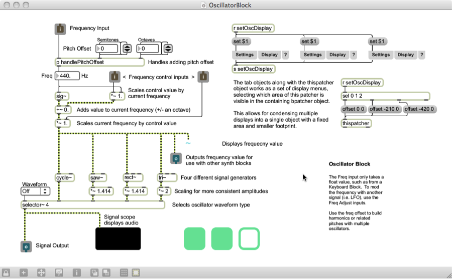
While the oscillator block may appear complex at first, there is a good bit of content that we added to improve the handling and display of the block for demonstrative and educational purposes. The objects grouped at the top right side of the patcher enable multiple display views for use within the bpatcher object. This is a useful and interesting feature of the bpatcher object, but we’re not going to focus on the nuts and bolts of it in this section. There is a simple example of this kind of implementation in the built-in bpatcher help file (Help > Open [ObjectName] Help in the file menu, or Right-click > Open [ObjectName] Help), so feel free to explore this further on your own. There are some additional objects and connections that are added to give additional display and informational feedback, such as the scope~ object that displays the audio waveform and a number~ object as a numerical display of the frequency, but these are relatively straightforward and non-essential to the design of this block. If we were to strip out all the objects and connections that don’t deal with audio or aren’t absolutely necessary for our synth block to work, it would look more like the file in Figure 6.48.

In its most basic functionality, the oscillator block simply generates an audio signal of some kind. In this case, we chose to provide several different options for the audio signal, including an object for generating basic sine waves (cycle~), sawtooth waves (saw~), square waves (rect~) and triangle waves (tri~). Each of these objects takes a number in to its leftmost inlet to set its frequency. The selector~ object is used to select between multiple signals, and the desired signal is passed through based on the waveform selected in the connected user interface dropdown menu (umenu). The inlets and outlets may seem strange when used in a standalone patcher file, and at this stage they aren’t really useful. However, when the file is linked into the bpatcher object, these inlets and outlets appear on the bpatcher and allow you access to these signals and control values in the main synth patcher.
While this module alone would enable you to begin synthesizing simple sounds, one of the purposes of the modular synthesizer blocks is to be able to wire them together to control each other in interesting ways. In this respect, we may want to consider ways to control or manipulate our oscillator block. The primary parameter in the case of the oscillator is the oscillator frequency, so we should incorporate some control elements for it. Perhaps we would want to increase or decrease the oscillator frequency, or even scale it by an external factor. Consider the way some of the software or hardware synths previously discussed in this chapter have manipulated the oscillator frequency. Looking back at the programming mode for this block, you may recall seeing several inlets labeled “frequency control” and some additional connected objects. A close view of these can be seen in Figure 6.49.
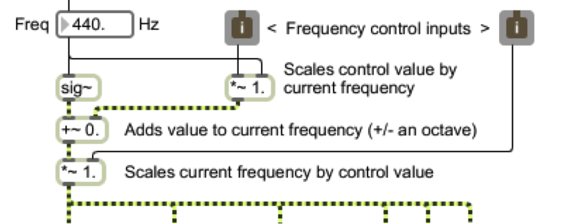
These control inputs are attached to several arithmetic objects, including addition and multiplication. The “~” following the mathematical operator simply means this version of the object is used for processing signal rate (audio) values. This is the sole purpose of the sig~ object also seen here; it takes the static numerical value of the frequency (shown at 440 Hz) and outputs it as a signal rate value, meaning it is constantly streaming its output. In the case of these two control inputs, we set one of them up as an additive control, and the other a multiplicative control. The inlet on the left is the additive control. It adds to the oscillator frequency an amount equal to some portion of the current oscillator frequency value. For example, if for the frequency value shown it receives a control value of 1, it adds 440 Hz to the oscillator frequency. If it receives a control value of 0.5, it adds 220 Hz to the oscillator frequency. If it receives a control value of 0, it adds nothing to the oscillator frequency, resulting in no change.
At this point we should take a step back and ask ourselves, “What kind of control values should we be expecting?” There is really no one answer to this, but as the designers of these synth blocks we should perhaps establish a convention that is meaningful across all of our different synthesizer elements. For our purposes, a floating-point range between 0.0 and 1.0 seems simple and manageable. Of course, we can’t stop someone from connecting a control value outside of this range to our block if they really wanted. That’s just what makes modular synthesis so fun.
Going back to the second control input (multiplicative), you can see that it scales the output of the oscillator directly by this control value. If it receives a control value of 0, the oscillator’s frequency is 0 and it outputs silence. If it receives a control value of 1, the signal is multiplied by 1, resulting in no change. Notice that the multiplication object has been set to a default value of 1 so that the initial oscillator without any control input behaves normally. The addition object has been initialized for that behavior as well. It is also very important to include the “.” with these initial values, as that tells the object to expect a floating-point value rather than an integer (default). Without the decimal, the object may round or truncate the floating-point value to the nearest integer, resulting in our case to a control value of either 0 or 1, which would be rather limiting.
Let’s now take a look at what goes into an amplification block. The amplification block is simply used to control the amplitude, or level, of the synthesized audio. Figure 6.50 shows you our amplifier block file in programming mode. There isn’t much need to strip down the non-essentials from this block, as there’s just not much to it.
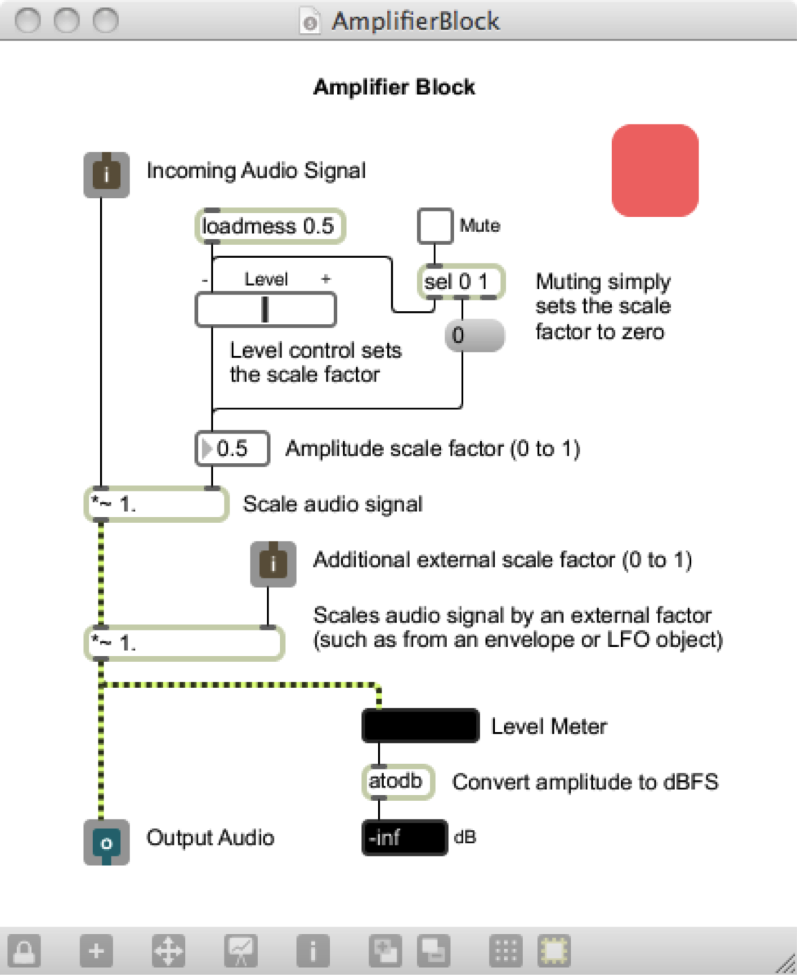
Tracing the audio signal path straight down the left side of the patcher, you can see that there are two stages of multiplication, which essentially is amplification in the digital realm. The first stage of amplification is controlled by a level slider and a mute toggle switch. These interface objects allow the overall amplification to be set graphically by the user. The second stage of amplification is set by an external control value. Again this is another good fit for the standard range we decided on of 0.0 to 1.0. A control value of 0 causes the signal amplitude to be scaled to 0, outputting silence. A control value of 1 results in no change in amplification. On the other hand, could you think of a reason we might want to increase the amplitude of the signal, and input a control value greater than 1.0? Perhaps a future synth block may have good reason to do this. Now that we have these available control inputs, we should start thinking of how we might actually control these blocks, such as with an envelope.
Figure 6.51 shows our envelope block in programming mode. Like the oscillator block, there are quite a few objects that we included to deal with additional display and presentational aspects that aren’t necessary to the block’s basic functionality. It too has a group of objects in the top right corner dedicated to enabling alternate views when embedded in the bpatcher object. If we were again to strip out all the objects and connections that don’t deal with audio or aren’t absolutely necessary for our synth block to work, it would look more like the file in Figure 6.52.
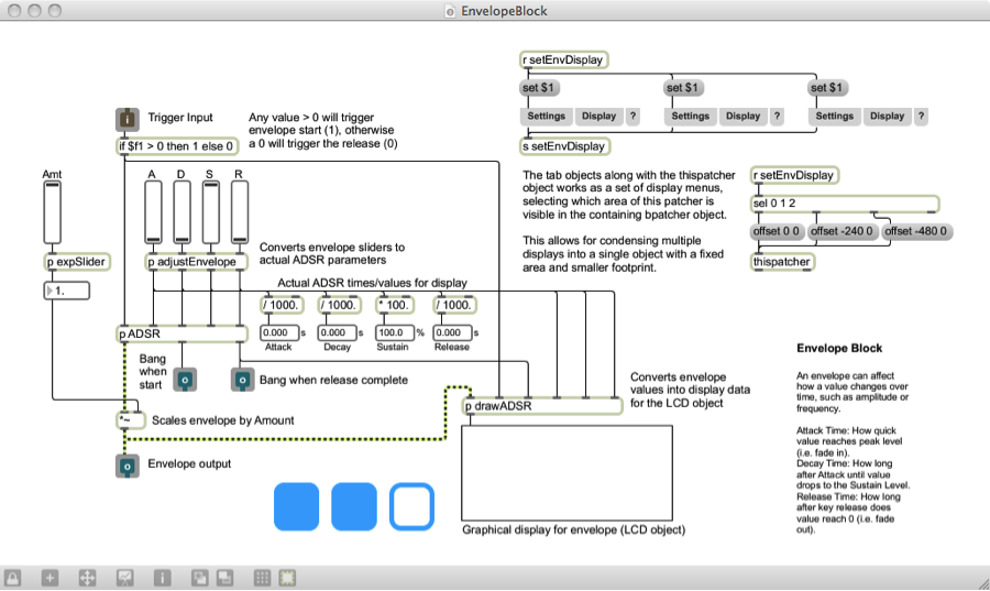

While it incorporates signal rate objects, the envelope doesn’t actually involve the audio signal. Its output is purely used for control. Then again, it’s possible for the user to connect the envelope block output to the audio signal path, but it probably won’t sound very good if it even makes a sound at all. Let’s start with the inlet at the top. In order for an envelope to function properly, it has to know when to start and when to stop. Typically it starts when someone triggers a note, such as by playing a key on a keyboard, and releases when the key is let go. Thinking back to MIDI and how MIDI keyboards work, we know that when a key is pressed, it sends a Note On command accompanied by a velocity value of between 1 and 127. When the key is released, it often sends a Note On command with a velocity value of zero. In our case, we don’t really care what the value is between 1 and 127; we need to start the envelope regardless of how hard the key is pressed.
This velocity value lends itself to being a good way to tell when to trigger and release an envelope. It would be useful to condition the input to give us only the two cases we care about: start and release. There are certainly multiple ways to implement this in MAX, but a simple if…then object is an easy way to check this logic using one object. The if…then object checks if the value at inlet 1 ($f1) is greater than 0 (as is the case for 1 to 127), and if so it outputs the value 1. Otherwise, (if the inlet value is less than or equal to 0) it outputs 0. Since there are no negative velocity values, we’ve just lumped them into the release outcome to cover our bases. Now our input value results in a 1 or a 0 relating to a start or release envelope trigger.
As is often the case, it just so happens that MAX has a built in adsr~ object that generates a standard ADSR envelope. We opted to create our own custom ADSR subpatcher. However, its purpose and inlets/outlets are essentially identical, and it’s meant to be easily interchangeable with the adsr~ object. You can find out more about our custom ADSR subpatcher and the reason for its existence in the MAX Demo “ADSR Envelopes” back in section 6.1.8.5.1. For the moment, we’ll refer to it as the standard adsr~ object.
Now, it just so happens that the adsr~ object’s first inlet triggers the envelope start when it sees any non-zero number, and it triggers the release when it receives a 0. Our input is thus already primed to be plugged straight into this object. It may also seem that our conditioning is now somewhat moot, since any typical velocity value, being a positive number, triggers the envelope start of the adsr~ object just as well as the number 1. It is however still important to consider that perhaps the user may (for creative reasons) connect a different type of control value to the envelope trigger input, other than note velocity. The conditioning if…then object thereby ensures a more widely successful operation with potentially unexpected input formats.
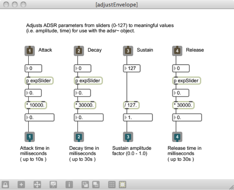
The adsr~ object also takes four other values as input. These are, as you might imagine, the attack time, decay time, sustain value, and release time. For simple controls, we’ve provided the user with four sliders to manipulate these parameters. In between the sliders and the adsr~ inlets, we need to condition the slider values to relate to usable ADSR values. The subpatcher adjustEnvelope does just that, and its contents can be seen in Figure 6.53. The four slider values (default 0 to 127) are converted to time values of appropriate scale, and in the case of sustain a factor ranging from 0.0 to 1.0. The expSlider subpatchers as seen in earlier MAX demos give the sliders an exponential curve, allowing for greater precision at lower values.
[wpfilebase tag=file id=48 tpl=supplement /][wpfilebase tag=file id=46 tpl=supplement /]
The generated ADSR envelope ranges from 0.0 to 1.0, rising and falling according to the ADSR input parameters. Before reaching the final outlet, the envelope is scaled by a user definable amount also ranging from 0.0 to 1.0, which essentially controls the impact the envelope has on the controllable parameter it is affecting.
It would too time-consuming to go through all of the modular synth blocks that we have created or that could potentially be created as part of this MAX example. However, these and other modular blocks can be downloaded and explored from the “Block Synthesizer” MAX demo linked at the start of this section. The blocks include the oscillator, amplifier, and envelope blocks discussed here, as well as a keyboard input block, LFO block, filter block, and a DAC block. Each individual block file is fully commented to assist you in understanding how it was put together. These blocks are all incorporated as bpatcher objects into a main BlockSynth.maxpat patcher, shown in Figure 6.54, where they can all be arranged, duplicated, and connected in various configurations to create a great number of synthesis possibilities. You can also check out the additional included BlockSynth_Example.maxpat and example settings files to see a few configurations and settings we came up with to create some unique synth sounds. Feel free to come up with your own synth blocks and implement them as well. Some possible ideas might be a metering block to provide additional displays and meters for the audio signal, a noise generator block for an alternative signal source or modulator, or perhaps a polyphony block to manage several instances of oscillator blocks and allow multiple simultaneous notes to be played.

Software synthesis is really the bedrock of the Max program, and you can learn a lot about Max through programming synthesizers. To that end, we have also created two Max programming exercises using our Subtractonaut synthesizer. These programming assignments challenge you to add some features to the existing synthesizer. Solution files are available that show how these features might be programmed.