6.2.5.1 MIDI Show Control
MIDI is not limited to use for digital music. There have been many additions to the MIDI specification to allow MIDI to be used in other areas. One addition is the MIDI Show Control Specification. MIDI Show Control (MSC) is used in live entertainment to control sound, lighting, projection, and other automated features in theatre, theme parks, concerts, and more.
MSC is a subset of the MIDI Systems Exclusive (SysEx) status byte. MIDI SysEx commands are typically specific to each manufacturer of MIDI devices. Each manufacturer gets a SysEx ID number. MSC has a SysEx sub-ID number of 0x02. The syntax, in hexadecimal, for a MSC message is:
F0 7F <device_ID> 02 <command_format> <command> <data> F7
- F0 is the status byte indicating the start of a SysEx message.
- 7F indicates the use of a SysEx sub-ID. This is technically a manufacturer ID that has been reserved to indicate extensions to the MIDI specification.
- <device_ID> can be any number between 0x00 and 0x7F indicating the device ID of the thing you want to control. These device ID numbers have to be set on the receiving end as well so each device knows which messages to respond to and which messages to ignore. 0x7F is a universal device ID. All devices respond to this ID regardless of their individual ID numbers.
- 02 is the sub-ID number for MIDI Show Control. This tells the receiving device that the bytes that follow are MIDI Show Control syntax as opposed to MIDI Machine Control, MIDI Time Code, or other commands.
- <command_format> is a number indicating the type of device being controlled. For example, 0x01 indicates a lighting device, 0x40 indicates a projection device, and 0x60 indicates a pyrotechnics device. A complete list of command format numbers can be found in the MIDI Show Control 1.1 specification.
- <command> is a number indicating the type of command being sent. For example, 0x01 is “GO”, 0x02 is “STOP”, 0x03 is “RESUME”, 0x0A is “RESET”.
- <data> represents a variable number of data bytes that are required for the type of command being sent. A “GO” command might need some data bytes to indicate the cue number that needs to be executed from a list of cues on the device. If no cue number is specified, the device simply executes the next cue in the list. Two data bytes (0x00, 0x00) are still needed in this case as delimiters for the cue number syntax. Some MSC devices are able to interpret the message without these delimiters, but they’re technically required in the MSC specification.
- F7 is the End of Systems Exclusive byte indicating the end of the message.
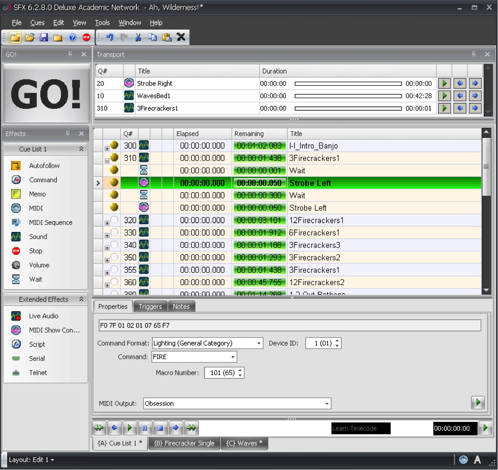
Most lighting consoles, projection systems, and computer sound playback systems used in live entertainment are able to generate and respond to MSC messages. Typically, you don’t have to create the commands manually in hex. You have a graphical interface that lets you choose the command you’re want from a list of menus. Figure 6.41 shows some MSC FIRE commands for a lighting console generated as part of a list of sound cues. In this case, the sound effect of a firecracker is synchronized with the flash of a strobe light using MSC.
6.2.5.2 MIDI Relays and Footswitches
You may not always have a device that knows how to respond to MIDI commands. For example, although there is a MIDI Show Control command format for motorized scenery, the motor that moves a unit on or off the stage doesn’t understand MIDI commands. However, it does understand a switch. There are many options available for MIDI controlled relays that respond to a MIDI command by making or breaking an electrical contact closure. This makes it possible for you to connect the wires for the control switch of a motor to the relay output, and then when you send the appropriate MIDI command to the relay, it closes the connection and the motor starts turning.
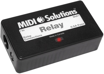
Another possibility is that you may want to use MIDI commands without a traditional MIDI controller. For example, maybe you want a sound effect to play each time a door is opened or closed. Using a MIDI footswitch device, you could wire up a magnetic door sensor to the footswitch input and have a MIDI command sent to the computer each time the door is opened or closed. The computer could then be programmed to respond by playing a sound file. Figure 6.42 shows an example of a MIDI relay device.
6.2.5.3 MIDI Time Code
MIDI sequencers, audio editors, and audio playback systems often need to synchronize their timeline with other systems. Synchronization could be needed for working with sound for video, lighting systems in live performance, and even automated theme park attractions. The world of filmmaking has been dealing with synchronization issues for decades, and the Society of Motion Picture and Television Engineers (SMPTE) has developed a standard format for a time code that can be used to keep video and audio in sync. Typically this is accomplished using an audio signal called Linear Time Code that has the synchronization data encoded in SMPTE format. The format is Hours:Minutes:Seconds:Frames. The number of frames per second varies, but the standard allows for 24, 25, 29.97 (also known as 30-Drop), and 30 frames per second.
MIDI Time Code (MTC) uses this same time code format, but instead of being encoded into an analog audio signal, the time information is transmitted in digital format via MIDI. A full MIDI Time Code message has the following syntax:
F0 7F <device_ID> <sub-ID 1> <sub-ID 2> <hr> <mn> <sc> <fr> F7
- F0 is the status byte indicating the start of a SysEx message.
- 7F indicates the use of a SysEx sub-ID. This is technically a manufacturer ID that has been reserved to indicate extensions to the MIDI specification.
- <device_ID> can be any number between 0x00 and 0x7F indicating the device ID of the thing you want to control. These device ID numbers have to be set on the receiving end as well so each device knows which messages to respond to and which messages to ignore. 0x7F is a universal device ID. All devices respond to this ID regardless of their individual ID numbers.
- <sub-ID 1> is the sub-ID number for MIDI Time Code. This tells the receiving device that the bytes that follow are MIDI Time Code syntax as opposed to MIDI Machine Control, MIDI Show Control, or other commands. There are a few different MIDI Time Code sub ID numbers. 01 is used for full SMPTE messages and for SMPTE user bits messages. 04 is used for a MIDI Cueing message that includes a SMPTE time along with values for markers such as Punch In/Out and Start/Stop points. 05 is used for real-time cuing messages. These messages have all the marker values but use the quarter-frame format for the time code.
- <sub-ID 2> is a number used to define the type of message within the sub-ID 1 families. For example, there are two types of Full Messages that use 01 for sub-ID 1. A value of 01 for sub-ID 2 in a Full Message would indicate a Full Time Code Message whereas 02 would indicate a User Bits Message.
- <hr> is a byte that carries both the hours value as well as the frame rate. Since there are only 24 hours in a day, the hours value can be encoded using the five least significant bits, while the next two greater significant bits are used for the frame rate. With those two bits you can indicate four different frame rates (24, 25, 29.97, 30). As this is a data byte, the most significant bit stays at 0.
- <mn> represents the minutes value 00-59.
- <sc> represents the seconds value 00-59.
- <fr> represents the frame value 00-29.
- F7 is the End of Systems Exclusive byte indicating the end of the message.
For example, to send a message that sets the current timeline location of every device in the system to 01:30:35:20 in 30 frames/second format, the hexadecimal message would be:
F0 7F 7F 01 01 61 1E 23 14 F7
Once the full message has been transmitted, the time code is sent in quarter-frame format. Quarter-frame messages are much smaller than full messages. This is less demanding of the system since only two bytes rather than ten bytes have to be parsed at a time. Quarter frame messages use the 0xF1 status byte and one data byte with the high nibble indicating the message type and the low nibble indicating the value of the given time field. There are eight message types, two for each time field. Each field is separated into a least significant nibble and a most significant nibble:
0 = Frame count LS
1 = Frame count MS
2 = Seconds count LS
3 = Seconds count MS
4 = Minutes count LS
5 = Minutes count MS
6 = Hours count LS
7 = Hours count MS and SMPTE frame rate
As the name indicates, quarter frame messages are transmitted in increments of four messages per frame. Messages are transmitted in the order listed above. Consequently, the entire SMPTE time is completed every two frames. Let’s break down the same 01:30:35:20 time value into quarter frame messages in hexadecimal. This time value would be broken up into eight messages:
F1 04  (Frame LS)
F1 11  (Frame MS)

F1 23  (Seconds LS)
F1 32  (Seconds MS)

F1 4E  (Minutes LS)
F1 51  (Minutes MS)

F1 61  (Hours LS)
F1 76  (Hours MS and Frame Rate)
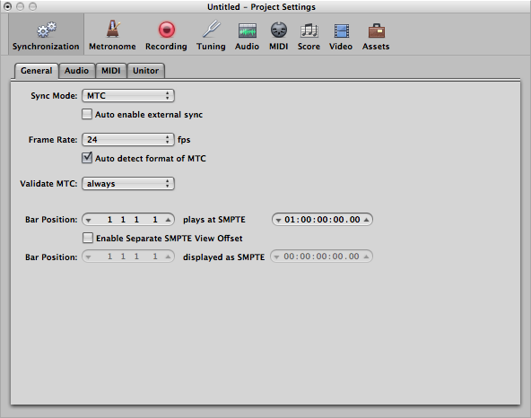
When synchronizing systems with MIDI Time Code, one device needs to be the master time code generator and all other devices need to be configured to follow the time code from this master clock. Figure 6.43 shows Logic Pro configured to synchronize to an incoming MIDI Time Code signal. If you have a mix of devices in your system that follow LTC or MTC, you can also put a dedicated time code device in your system that collects the time code signal in LTC or MTC format and then relay that time code to all the devices in your system in the various formats required, as shown in Figure 6.44.
6.2.5.4 MIDI Machine Control
[wpfilebase tag=file id=44 tpl=supplement /]
Another subset of the MIDI specification is a set of commands that can control the transport system of various recording and playback systems. Transport controls are things like play, stop, rewind, record, etc. This command set is called MIDI Machine Control. The specification is quite comprehensive and includes options for SMPTE time code values, as well as confirmation response messages from the devices being controlled. A simple MMC message has the following syntax:
F0 7F <device_ID> 06 <command> F7
- F0 is the status byte indicating the start of a SysEx message.
- 7F indicates the use of a SysEx sub-ID. This is technically a manufacturer ID that has been reserved to indicate extensions to the MIDI specification.
- <device_ID> can be any number between 0x00 and 0x7F indicating the device ID of the thing you want to control. These device ID numbers have to be set on the receiving end as well so each device knows which messages to respond to and which messages to ignore. 0x7F is a universal device ID. All devices respond to this ID regardless of their individual ID numbers.
- 06 is the sub-ID number for MIDI Machine Control. This tells the receiving device that the bytes that follow are MIDI Machine Control syntax as opposed to MIDI Show Control, MIDI Time Code, or other commands.
- <command> can be a set of bytes as small as one byte and can include several bytes communicating various commands in great detail. A simple play (0x02) or stop (0x01) command only requires a single data byte.
- F7 is the End of Systems Exclusive byte indicating the end of the message.
A MMC command for PLAY would look like this:
F0 7F 7F 06 02 F7
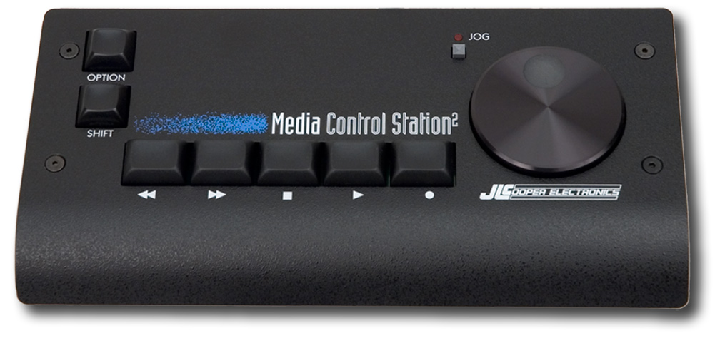
MIDI Machine Control was really a necessity when most studio recording systems were made up of several different magnetic tape-based systems or dedicated hard disc recorders. In these situations, a single transport control would make sure all the devices were doing the same thing. In today’s software-based systems, MIDI Machine Control is primarily used with MIDI control surfaces, like the one shown in Figure 6.45, that connect to a computer so you can control the transport of your DAW software without having to manipulate a mouse.