6.1.8.1 Presets
Now let’s take a closer look at synthesizers. In this section, we’re referring to synthesizers in the strict sense of the word – those that can be programmed to create sounds dynamically, as opposed to using recorded samples of real instruments. Synthesizer programming entails selecting an initial patch or waveform, filtering it, amplifying it, applying envelopes, applying low frequency oscillators to shape the amplitude or frequency changes, and so forth, as we’ll describe below. There are many different forms of sound synthesis, but they all use the same basic tools to generate the sounds. The difference is how the tools are used and connected together. In most cases, the software synthesizer comes with a large library of pre-built patches that configure the synthesizer to make various sounds. In your own work, you’ll probably use the presets as a starting point and modify the patches to your liking. Once you learn to master the tools, you can start building your own patches from scratch to create any sound you can imagine.
6.1.8.2 Sound Generator
The first object in the audio path of any synthesizer is the sound generator. Regardless of the synthesis method being used, you have to start by creating some sort of sound that is then shaped into the specific sound you’re looking for. In most cases, the sound generator is made up of one or more oscillators that create simple sounds like sine, sawtooth, triangle, and square waves. The sound generator might also consist of a noise generator that plays pink noise or white noise. You might also see a wavetable oscillator that can play a pre-recorded complex shape. If your synthesizer has multiple sound generators, there is also some sort of mixer that merges all the sounds together. Depending on the synthesis method being used, you may also have an option to decide how the sounds are combined (i.e. through addition, multiplication, modulation, etc.). Because synthesizers are most commonly used as musical instruments, there typically is a control on the oscillator that adjusts the frequency of the sound that is generated. This frequency can usually be changed remotely over time but typically, you choose some sort of starting point and any pitch changes are applied relative to the starting frequency. Figure 6.21 shows an example of a sound generator. In this case we have two oscillators and a noise generator. For the oscillators you can select the type of waveform to be generated. Instead of your being allowed to control the pitch of the oscillator in actual frequency values, the default frequency is defined by the note A (according to the manual). You get to choose which octave you want the A to start in and can further tune up or down from there in semitones and cents. An option included in a number of synthesizer components is keyboard tracking, which allows you to control how a parameter is set or a feature is applied depending on which key on the keyboard is pressed. The keyboard tracking (Kbd. Track) button in our example sound generator defines whether you want the oscillator’s frequency to change relative to the MIDI note number coming in from the MIDI controller. If this button is off, the synthesizer plays the same frequency regardless of the note played on the MIDI controller. The Phase, FM, Mix, and Mode controls determine the way these two oscillators interact with each other.

6.1.8.3 Filters
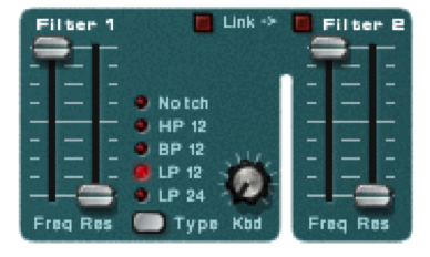
A filter is another object that is often found in the audio path. A filter is an object that modifies the amplitude of specified frequencies in the audio signal. There are several types of filters. In this section, we describe the basic features of filters most commonly found in synthesizers. For more detailed information on filters, see Chapter 7. Low-pass filters attempt to remove all frequencies above a certain point defined by the filter cutoff frequency. There is always a slope to the filter that defines the rate at which the frequencies are attenuated above the cutoff frequency. This is often called the filter order. A first order filter attenuates frequencies above the cutoff frequency at the rate of 6 dB per octave. If your cutoff frequency is 1 kHz, a first order filter attenuates 2 kHz by -6dB below the cutoff frequency, 4 kHz by -12 dB, 8 kHz by -18 dB, etc. A second order filter attenuates 12 dB per octave, a third order filter is 18 dB per octave, and a fourth order is 24 dB per octave. In some cases, the filter order is fixed, but more sophisticated filters allow you to choose the filter order that is the best fit for the sound you’re looking for. The cutoff frequency is typically the frequency that has been attenuated -6 dB from the level of the frequencies that are unaffected by the filter. The space between the cutoff frequency and frequencies that are not affected by the filter is called the filter typography. The typography can be shaped by the filter’s resonance control. Increasing the filter resonance creates a boost in the frequencies near the cutoff frequency. High-pass filters are the opposite of low-pass. Instead of removing all the frequencies above a certain point, a high-pass filter removes all the frequencies below a certain point. A high-pass filter has a cutoff frequency, filter order, and resonance control just like the low-pass filter. Bandpass filters are a combination of a high-pass and low-pass filter. A bandpass filter has a low cutoff frequency and a high cutoff frequency with filter order and resonance controls for each. In some cases, a bandpass filter is implemented with a fixed bandwidth or range of frequencies between the two cutoff frequencies. This simplifies the number of controls needed because you simply need to define a center frequency that positions the bandpass at the desired location in the frequency spectrum. Bandstop filters (also called notch filters) creates a boost or cut of a defined range of frequencies. In this case the filter frequency defines the center of the notch. You might also have a bandwidth control that adjusts the range of frequencies to be boosted or cut. Finally, you have a control that adjusts the amount of change applied to the center frequency. Figure 6.22 shows the filter controls in our example synthesizer. In this case we have two filters. Filter 1 has a frequency and resonance control and allows you to select the type of filter. The filter type selected in the example is a low-pass second order (12 dB per octave) filter. This filter also has a keyboard tracking knob where you can define the extent to which the filter cutoff frequency is changed relative to different frequencies. When you set the filter cutoff frequency using a specific key on the keyboard, the filter is affecting harmonic frequencies relative to the fundamental frequency of the key you pressed. If you play a key one octave higher, the new fundamental frequency generated by the oscillator is the same as the first harmonic of the key you were pressing when you set the filter. Consequently, the timbre of the sound changes as you move to higher and lower frequencies because the filter frequency is not changing when the oscillator frequency changes. The filter keyboard tracking allows you to change the cutoff frequency of the filter relative to the key being pressed on the keyboard. As you move to lower notes, the cutoff frequency also lowers. The knob allows you to decide how dramatically the cutoff frequency gets shifted relative to the note being pressed. The second filter is a fixed filter type (second order low-pass) with its own frequency and resonance controls and has no keyboard tracking option.
We’ll discuss the mathematics of filters in Chapter 7.
6.1.8.4 Signal Amplifier
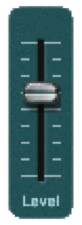
The last object in the audio path of a synthesizer is a signal amplifier. The amplifier typically has a master volume control that sets the final output level for the sound. In the analog days this was a VCA (Voltage Controlled Amplifier) that allowed the amplitude of the synthesized sound to be controlled externally over time. This is still possible in the digital world, and it is common to have the amplifier controlled by several external modulators to help shape the amplitude of the sound as it is played. For example, you could control the amplifier in a way that lets the sound fade in slowly instead of cutting in quickly.
6.1.8.5 Modulation
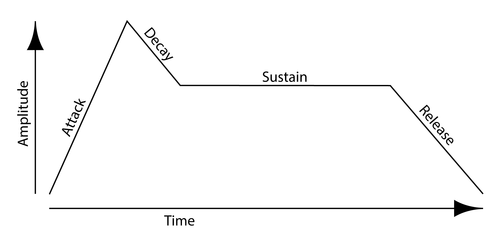
Modulation is the process of changing a shape of a waveform over time. This is done by continuously changing one of the parameters that defines the waveform by multiplying it by some coefficient. All the major parameters that define a waveform can be modulated, including its frequency, amplitude, and phase. A graph of the coefficients by which the waveform is modified shows us the shape of the modulation over time. This graph is sometimes referred to as an envelope that is imposed over the chosen parameter, giving it a continuously changing shape. The graph might correspond to a continuous function, like a sine, triangle, square, or sawtooth. Alternative, the graph might represent a more complex function, like the ADSR envelope illustrated in Figure 6.25 illustrates a particular type of envelope, called ADSR. We’ll see look at mathematics of amplitude, phase, and frequency modulation in Section 3. For now, we’ll focus on LFOs and ADSR envelopes, commonly-used tools in synthesizers.
6.1.8.6 LFO
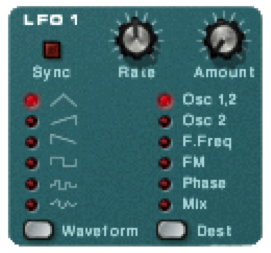
LFO stands for low frequency oscillator. An LFO is simply an oscillator just like the ones found in the sound generator section of the synthesizer. The difference here is that the LFO is not part of the audio path of the synthesizer. In other words, you can’t hear the frequency generated by the LFO. Even if the LFO was put into the audio path, it oscillates at frequencies well below the range of human hearing so it isn’t heard anyway. A LFO oscillates anywhere from 10 Hz down to a fraction of a Hertz. LFO’s are used like envelopes to modulate parameters of the synthesizer over time. Typically you can choose from several different waveforms. For example, you can use an LFO with a sinusoidal shape to change the pitch of the oscillator over time, creating a vibrato effect. As the wave moves up and down, the pitch of the oscillator follows. You can also use an LFO to control the sound amplitude over time to create a pulsing effect. Figure 6.24 shows the LFO controls on a synthesizer. The Waveform button toggles the LFO between one of six different waveforms. The Dest button toggles through a list of destination parameters for the LFO. Currently, the LFO is set to create a triangle wave and apply it to the pitch of Oscillators 1 and 2. The Rate knob defines the frequency of the LFO and the Amount knob defines the amplitude of the wave or the amount of modulation that is applied. A higher amount creates a more dramatic change to the destination parameter. When the Sync button is engaged, the LFO frequency is synchronized to the incoming tempo for your song based on a division defined by the Rate knob such as a quarter note or a half note.
6.1.8.7 Envelopes
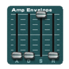
[wpfilebase tag=file id=42 tpl=supplement /] The attack and decay values control how the sound begins. If the attack is set to a positive value, the sound fades in to the level defined by the master volume level over the period of time indicated in the attack. When the attack fade-in time completes, the amplitude moves to the sustain level. The decay value defines how quickly that move happens. If the decay is set to the lowest level, the sound jumps instantly to the sustain level once the attack completes. If the decay time has a positive value, the sound slowly fades down to the sustain level over the period of time defined by the decay after the attack completes.Most synthesizers have at least one envelope object. An envelope is an object that controls a synthesizer parameter over time. The most common application of an envelope is an amplitude envelope. An amplitude envelope gets applied to the signal amplifier for the synthesizer. Envelopes have four parameters: attack time, decay time, sustain level, and release time. The sustain level defines the amplitude of the sound while the note is held down on the keyboard. If the sustain level is at the maximum value, the sound is played at the amplitude defined by the master volume controller. Consequently, the sustain level is typically an attenuator that reduces rather than amplifies the level. If the other three envelope parameters are set to zero time, the sound is simply played at the amplitude defined by the sustain level relative to the master volume level. The release time defines the amount of time it takes for the sound level to drop to silence after the note is released. You might also call this a fade-out time. Figure 6.25 is a graph showing these parameters relative to amplitude and time. Figure 6.26 shows the amplitude envelope controls on a synthesizer. In this case, the envelope is bypassed because the sustain is set to the highest level and everything else is at the lowest value.
Envelopes can be used to control almost any synthesizer parameter over time. You might use an envelope to change the cutoff frequency of a filter or the pitch of the oscillator over time. Generally speaking, if you can change a parameter with a slider or a knob, you can modulate it over time with an envelope.
6.1.8.8 MIDI Modulation
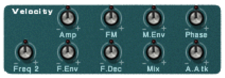
You can also use incoming MIDI commands to modulate parameters on the synthesizer. Most synthesizers have a pre-defined set of MIDI commands it can respond to. More powerful synthesizers allow you to define any MIDI command and apply it to any synthesizer parameter. Using MIDI commands to modulate the synthesizer puts more power in the hands of the performer. Here’s an example of how MIDI modulation can work. Piano players are used to getting a different sound from the piano depending on how hard they press the key. To recreate this touch sensitivity, most MIDI keyboards change the velocity value of the Note On command depending on how hard the key is pressed. However, MIDI messages can be interpreted in whatever way the receiver chooses. Figure 6.27 shows how you might use velocity to modulate the sound in the synthesizer. In most cases, you would expect for the sound to get louder when the key is pressed harder. If you increase the Amp knob in the velocity section of the synthesizer, the signal amplifier level increases and decreases with the incoming velocity information. In some cases, you might also expect to hear more harmonics with the sound if the key is pressed harder. Increasing the value for the F.Env knob adjusts the depth at which the filter envelope is applied to the filter cutoff frequency. A higher velocity means that the filter envelope makes a more dramatic change to the filter cutoff frequency over time.
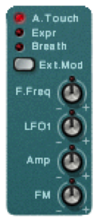
Some MIDI keyboards can send After Touch or Channel Pressure commands if the pressure at which the key is held down changes. You can use this pressure information to modulate a synthesizer parameter. For example, if you have a LFO applied to the pitch of the oscillator to create a vibrato effect, you can apply incoming key pressure data to adjust the LFO amount. This way the vibrato is only applied when the performer desires it by increasing the pressure at which he or she is holding down the keys. Figure 6.28 shows some controls on a synthesizer to apply After Touch and other incoming MIDI data to four different synthesizer parameters.