Max (distributed by Cycling ‘74 and formerly called Max/MSP/Jitter) is a software environment for manipulating digital audio and MIDI data. The interface for Max is at a high level of abstraction, allowing you to patch together sound objects by dragging icons for them to a window and linking them with patcher cords, similar to the way audio hardware is connected. If you aren’t able to use Max, which is a commercial product, you can try substituting the freeware program Pure Data. We introduce you briefly to Pure Data in Section 2.3.2. In future chapters, we’ll limit our examples to Max because of its highly developed functionality, but PD is a viable free alternative that you might want to try.
[wpfilebase tag=file id=27 tpl=supplement /]
Max can be used in two ways. First, it’s an excellent environment for experimenting with sound simply to understand it better. As you synthesize and analyze sound through built-in Max objects and functions, you develop a better understanding of the event-driven nature of MIDI versus the streaming data nature of digital audio, and you see more closely how these kinds of data are manipulated through transforms, effects processors, and the like. Secondly, Max is actually used in the sound industry. When higher level audio processing programs like Logic, Pro Tools, Reason, or Sonar don’t meet the specific needs of audio engineers, they can create specially-designed systems using Max.
Max is actually a combination of two components that can be made to work together. Max allows you to work with MIDI objects, and MSP is designed for digital audio objects. Since we won’t go into depth in MIDI until Chapter 6, we’ll just look at MSP for now.
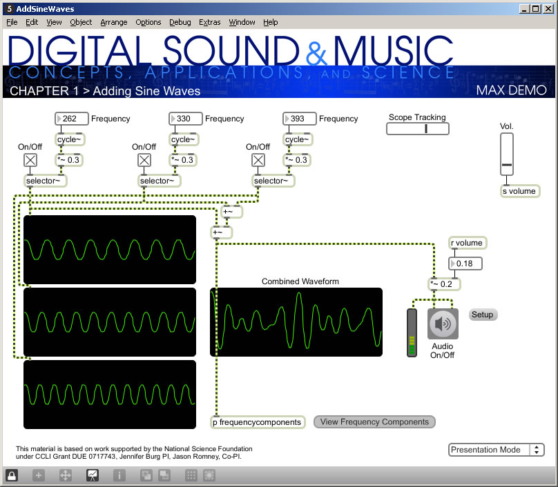
Let’s try a simple example of MSP to get you started. Figure 2.38 shows an MSP patcher for adding three pure sine waves. A patcher – whether it has Max objects, MSP objects, or both – is a visual representation of a program that operates on sound. The objects are connected by patch cords. These cords run between the inlets and outlets of objects.
One of the first things you’ll probably want to do in MSP is create simple sine waves and listen to them. To be able to work on a patcher, you have to be in edit mode, as opposed to lock mode. You enter edit mode by clicking CTRL-E (or Apple-E) or by clicking the lock icon on the task bar. Once in edit mode, you can click on the + icon on the task bar, which gives you a menu of objects. (We refer you to the Max Help for details on inserting various objects.) The cycle~ object creates a sine wave of whatever frequency you specify.
Notice that MSP objects are distinguished from Max objects by the tilde at the end of their names. This reminds you that MSP objects send audio data streaming continuously through them, while Max objects typically are triggered by and trigger discrete events.
The speaker icon in Figure 2.24 represents the ezdac~ object, which stands for “easy digital to analog conversion,” and sends sound to the sound card to be played. A number object sends the desired frequency to each cycle~ object, which in turn sends the sine wave to a scope~ object (the sine wave graphs) for display. The three frequencies are summed with two consecutive +~ objects, and the resulting complex waveform is displayed.
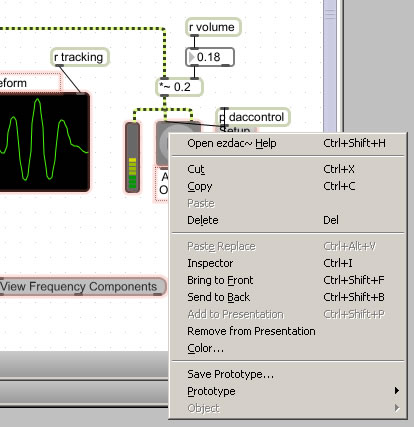
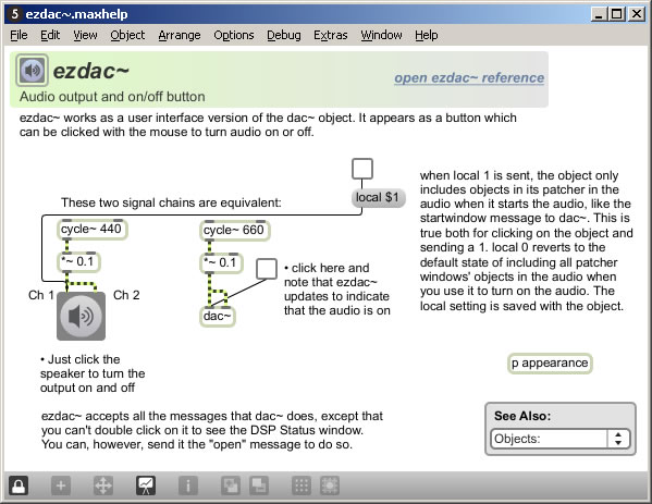
To understand these objects and functions in more detail, you can right click on them to get an Inspector window, which shows the parameters of the objects. Figure 2.25 shows the inspector for the meter~ object, which looks like an LED and is to the left of the Audio On/Off switch in Figure 2.24. You can change the parameters in the Inspector as you wish. You also can right click on an object, go to the Help menu (Figure 2.26), and access an example patcher that helps you with the selected object. Figure 2.27 shows the Help patcher for the ezdac~ object. The patchers in the Help can be run as programs, opened in Edit mode, and copied and pasted into your own patchers.

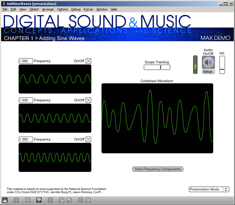
When you create a patcher, you may want to define how it looks to the user in what is called presentation mode, a view in which you can hide some of the implementation details of the patcher to make its essential functionality clearer. The example patcher’s presentation mode is shown in Figure 2.28.